Installation Guide
Wiring the TLS RF
12
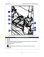
LEGEND FOR NUMBERED BOXES
IN FIGURE 8
1.
POWER WIRING NOTES:
- Barrier ground must be #12
AWG or larger diameter.
- Check to be sure that the
electrical resistance - between
the unit ground lug and a
known good earth ground is
less than 1 ohm.
- Connect the power supply
wires in the power panel to a
separate dedicated circuit.
- Electrical rating power input
- 120 Vac or 240 Vac, 50/60 Hz,
2 A max.
- See Figure 3 for actual
locations of power conduit
knockouts into the unit. Power
wiring must enter only in one
of these knockouts.
2.
AC power input wires (#14
AWG) to AC input terminals.
3.
Protective earthing conductor
(green and yellow). Attach
#12AWG barrier ground wire
to ground lug. Ground must be
the same as the supply and
less than 1.0 ohms to ground.
4.
Attach chassis ground wire
(#14 AWG) to ground lug.
5.
Connect the shield of the RS-
485 cable to the ground lug.
6.
RS-485 cable from master TLS
RF.
7.
See Figure 9 for connections.
Figure 8. Power connections to a daisy chained TLS RF
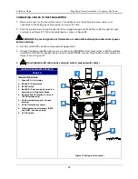
1.
TLS RF Master
2.
RS-485 cable to Receiver.
3.
RS-485 cable to TLS RF. Cut
the unused twisted pair back
to the cable’s jacket at each
end of the cable.
4.
TLS RF Auxiliary
5.
Connect the shield of the RS-
485 cable to the ground lug.
6.
Connect like colored wires of
the twisted pair to like
Figure 9. RS-485 cable connections when daisy chaining two TLS RFs


