Veeder-Root Red Jacket FXT Скачать руководство пользователя страница 19

Testing Procedures

Manifolded Pumps with Leak Detectors

15

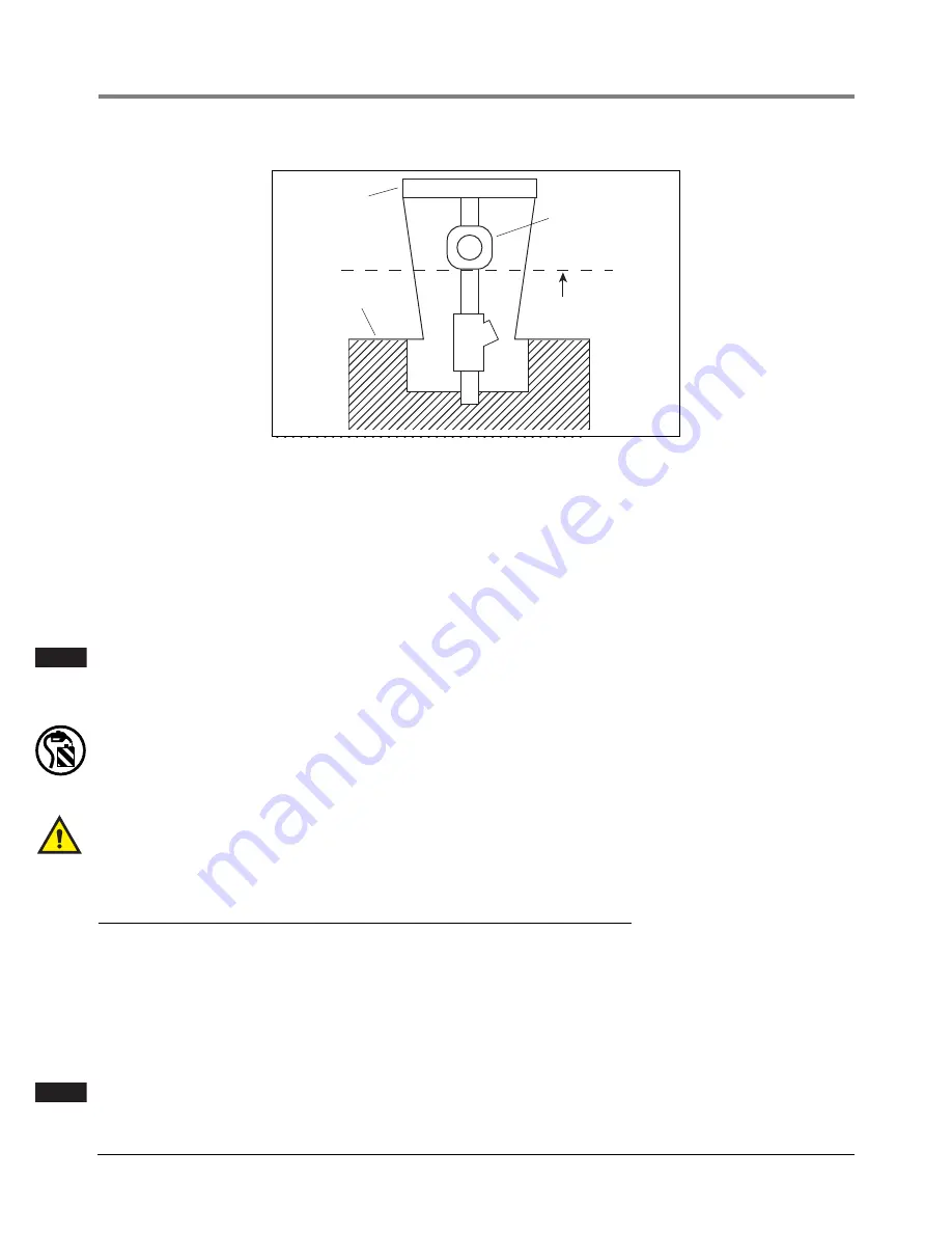
Figure 6.   Discharge fluid height limit example

By raising the discharge point of the simulated leak from the FXT above the test area, additional static head is 
placed on the LLD. Static head is defined as the pressure exerted on the LLD by the vertical column of fluid 
contained within the piping, from the LLD upward to the point of discharge of the leak. By placing the point of 
discharge high enough above the island, sufficient static head pressure could be placed upon the LLD to keep 
it from entering the leak sensing position. It is assumed that piping from the LLD to the point of discharge is a 
continual, gradual, upward or positive run and does not have a negative (declining) run. 

For more information on static head effects, please see Red Jacket Service Bulletin 23-5 and 23-18 or the ap-
plication section of the mechanical leak detector manual covering the effects of static head on mechanical leak 
detectors.

If the LLD or pumping system operation differs significantly from that described in this manual, 
see leak detector manual #5191 and/or Petroleum Products Service Manual #5190, for possible 
causes and solutions.

3.

Plug the FXT into the Snap-Tap on the dispenser shear valve as shown in Figure 5 on page 14.

CAUTION! To avoid product spillage, assure the discharge is directed into a suitable container.

4.

A leak check may now be performed by following “Simulated Leak Test - 4 Step Test” on page 7. In this case, 
product is not being returned directly to the tank via the Snap-Tap fitting on the pump but is collected in the 
container.

Snap Tap connectors shall not be left permanently installed into the impact/shear valves and must be 
removed upon completion of testing.

Manifolded Pumps with Leak Detectors

For manifolded systems that have two LLDs on a single line and the pumps operate simultaneously, testing must 
be performed at the impact valve, as shown in Figure 5.

The minimum leak detectable will be the sum of the two LLD’s capabilities; typically 6 - 7 gph at 10 psi (23-26 lph 
at 69 kPa).

If the minimum leak detectable is unacceptable, the LLDs may be tested individually by having only one pump 
come on during the test. This will help in determining which LLD is causing the unacceptable rate.

Pumps must be activated simultaneously in manifolded systems. If they alternate, LLDs cannot be 
accurately tested.

Dispenser

Grade

Solenoid

Do not discharge
fluid above this line

rj\fxt1.eps

NOTE

G
    A
       S

NOTE

Содержание Red Jacket FXT

Страница 1: ...Manual No C051 272 Revision E Testing Mechanical Leak Detectors FX Tester...

Страница 2: ...f any damages and or shortages within 30 days of receipt of the shipment as stated in our Terms and Conditions VEEDER ROOT S PREFERRED CARRIER 1 Fax Bill of Lading to V R Customer Service at 800 234 5...

Страница 3: ...Extender Hoses 7 Simulated Leak Test 4 Step Test 7 Observation of Leak Detector Opening Time 10 Operating Test Pressure Relief 11 Pump Operation 11 Thermal Contraction 12 Vacuum Test 12 To Perform A...

Страница 4: ...to the Red Jacket pump 8 Figure 4 FXT selector valve 9 Figure 5 Installing Snap Tap at shear valve 14 Figure 6 Discharge fluid height limit example 15 Figure 7 FX Tester operating positions 16 Figure...

Страница 5: ...echanical Leak Detector Manual 5191 and or 5190 Option A utilizing the Apparatus to Verify Operation AVO will provide a more basic less extensive approach to evaluating the V R LLD See Form RJ 21 for...

Страница 6: ...e entire pumping system and of replacement of the LLD versus continued use We nave no control influence or participation with reference to the design operation or quality of any mechanical leak detect...

Страница 7: ...and follow the instructions Follow the Regulations Applicable information is available in National Fire Protection Association NFPA 30A Code for Motor Field Dispensing Facilities and Repair Garages N...

Страница 8: ...azardous Materials Some materials may present a health hazard if not handled correctly Ensure that you clean hands after handling equipment Do not place any equipment in the mouth WARNING FAILURE TO C...

Страница 9: ...hest from the pump and working to the pump until all air is removed from system Certain regulatory bodies require that leak detectors remain in the system after the lines have been installed The lines...

Страница 10: ...ld height and then closed before the pump is turned on Under normal operations the leak detector will hesitate at the metering pressure for several seconds before opening up to full pump pressure With...

Страница 11: ...See Parts Description Replacement Parts List on page 18 Simulated Leak Test 4 Step Test This is a general overview of the procedure to properly install the FXT and how to set a leak rate at a given p...

Страница 12: ...shown in Figure 4 When the selector valve is in this position the FXT is monitoring actual line pressure As actual line pressure is displayed on the compound gauge specifications can be checked d Obse...

Страница 13: ...PH 7 GPH 8 GPH 9 GPH 10 GPH 20 4 2 5 7 7 1 8 5 9 9 11 3 12 7 14 1 22 4 4 5 9 7 4 8 9 10 4 11 9 13 3 14 8 24 4 6 6 2 7 7 9 3 10 8 12 4 13 9 15 5 26 4 8 6 4 8 1 9 7 11 3 12 9 14 5 16 1 28 5 0 6 7 8 4 10...

Страница 14: ...ies FX1 Series or FX2 Series LLDs indicates that the LLD has reacted to the imposed leak and is in its leak sensing mode A Pressure of approximately 25 psi 172 kPa or greater indicates that the LLD di...

Страница 15: ...used a holding pressure of between 8 to 20 psi 55 138 kPa is normally observed If a precision functional element is used a holding pressure of about 11 to 13 5 psi 76 93 kPa should be observed Adjust...

Страница 16: ...e the LLD will interpret an open nozzle as a line leak In the summer months thermal contraction of the product throughout the day rarely occurs The line pressure may only drop to zero once a day usual...

Страница 17: ...Attach the orange pressure hose to the FX2 leak detector 2 Turn the submersible pump on and then off 3 Turn the FXT s Selector Valve slowly to the Pressure Relief position as product begins to flow i...

Страница 18: ...e im pact valve This reducer is not called out in the parts list Loss of product as well as introduction of air into the system can be minimized by closing the emergency valve previous to removing the...

Страница 19: ...ce Manual 5190 for possible causes and solutions 3 Plug the FXT into the Snap Tap on the dispenser shear valve as shown in Figure 5 on page 14 CAUTION To avoid product spillage assure the discharge is...

Страница 20: ...hat the leak is present If there are no leaks pressure rapidly builds in the system forcing the LLD to open to the full flow position In a system with no leaks it takes approximately 2 3 seconds for t...

Страница 21: ...he 1 1 2 to 3 gpm 5 11 lpm will flow to the dispensers Leaks smaller than 3 gph will be indicated by the LLD taking longer than 2 3 seconds to open completely If there is no leakage in the system the...

Страница 22: ...ap Tap Orange N S 138 209 4 6 Swagelok Tube Connection Deso Stem 014 697 1 Extender Hose Only Orange N S 038 213 1 7 Swivel Connector 9 16 In Swivel Hex 9 16 In Hex 027 241 1 20 Bumper 006 729 1 8 Bul...

Страница 23: ...ot regarding the use and maintenance of the FX Tester is that this equipment should be periodically compared against standards which are traceable to the National Institute of Standards and Technology...

Страница 24: ...19 with countersink holes facing up to upper and lower blocks 1 13 with eight screws 18 four each side Ensure connectors 13 are facing same direction Torque 8 in lbs 4 Turn locking screw 21 in top bl...

Страница 25: ...with desired units facing up Align zero mark on scale 14 with zero mark on flowtube 9 Place clear cover 20 with countersink holes facing up align holes and secure with four screws 18 Torque 2 5 3 in l...

Страница 26: ..._______________ Technician Performing Test _______________________________________________ TECH Number ____________________ TYPES OF LEAK DETECTORS TESTED BFLD 117 182 5 FX2V 116 057 5 FX2DV 116 059 5...

Страница 27: ...___________________________ TECH Number ____________________ TYPES OF LEAK DETECTORS TESTED BFLD 117 182 5 FX2V 116 057 5 FX2DV 116 059 5 FX1V 116 056 5 FX1DV 116 058 5 TEST INFORMATION Product Serial...

Страница 28: ...____________________________ TECH Number ____________________ TYPES OF LEAK DETECTORS TESTED BFLD 117 182 5 FX2V 116 057 5 FX2DV 116 059 5 FX1V 116 056 5 FX1DV 116 058 5 TEST INFORMATION Product Seria...

Страница 29: ...For technical support sales or other assistance please visit www veeder com...

Отзывы: