8
EMR
3
- Truck Installations
EMR4 Truck Installation
Input Power – Critical Ground Connection
2-STAGE SOLENOID VALVE CONNECTIONS
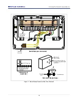
A 2-stage solenoid flow valve is shown in Figure 4 and wiring connections in Table 1.
Figure 4. 2-Stage Solenoid Valve
VALVE OPERATION WITH THE EMR4
Full Flow
The valve is normally closed. When the START button is pushed on the EMR4 display, both relays for that head are
energized, opening the solenoid-operated valves. The Fast Flow solenoid valve allows the main valve diaphragm to
open via the pump pressure pushing on the diaphragm. Full flow is obtained. The Slow Flow solenoid valve allows
flow around the main diaphragm valve. When the FINISH button is pushed on the EMR4 display, both relays are
de-energized, the solenoid valves close stopping flow.
Preset
The valve is normally closed. When the START button is pushed on the EMR4 display, both relays for that head are
energized, opening the solenoid valves and fast/full flow is obtained.
• First Stage Knockoff - When the first stage/slow flow point is reached (1st stage knockoff), the fast flow/relay 1
de-energizes and the spring assisted main diaphragm of the valve closes as the pressure equalizes. The single
flow/relay 2 bypass remains open for slow flow.
Table 1. 2-Stage Solenoid Wiring
Display Head
Relay Function
Diagram In
Installation Manual
Setup Manual
Head 1
DH1-R2
COM
Relay Control
Set Advance Stop
(2nd Stage
Knockoff)
N.O.
DH1-R1
COM
Relay Control
Set Slow Flow
(1st Stage
Knockoff)
N.O.
Head 2
DH2-R2
COM
Relay Control
Set Advance Stop
(2nd Stage
Knockoff)
N.O.
DH2-R1
COM
Relay Control
Set Slow Flow
(1st Stage
Knockoff)
N.O.
Single Flow In IB
(Relay 2)
Flow
(Solenoid Valve
Number Begins
With 7221)
(Solenoid Valve
Number Begins
With 7121)
Fast Flow In IB
(Relay 1)
DH 1
Relays
C
N.O.
Single
Flow
C
N.O.
Fast
Flow
DH 2
Relays
C
N.O.
Single
Flow
C
N.O.
Fast
Flow


