EMR
3
Setup and Operation Manual
Setup Mode Categories
26
Port 2 Assign
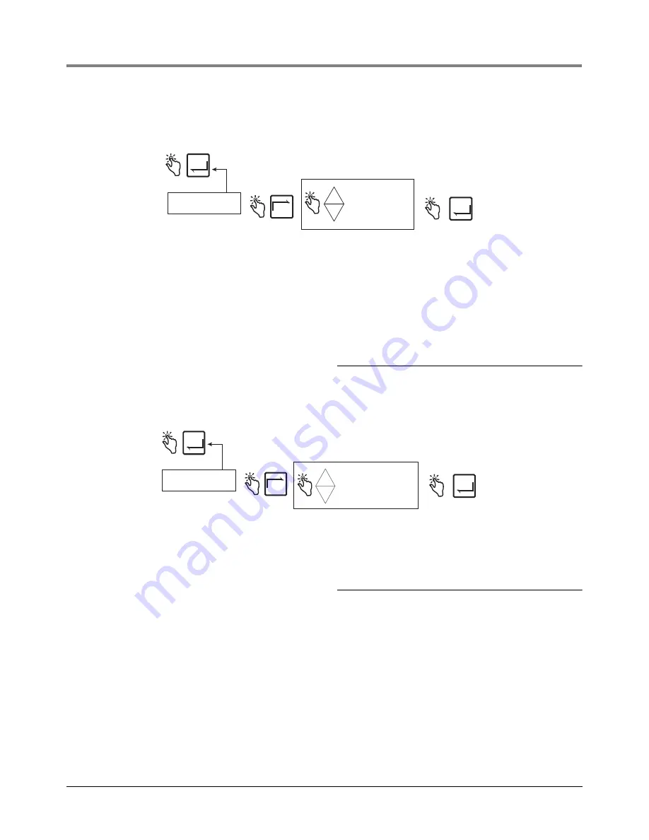
Figure 27 illustrates Port 2 Assign setup choices.
Figure 27. Port 2 Assign Setup
Head Address
Figure 28 illustrates Head Address setup choices (note Caution in figure below).
Figure 28. Head Address Setup
Initial Remote Display Setup
Connect the cable from the Master Display Head to the DH#1 connector located in the IB box. Once powered,
enter the Setup Mode and set the Head Address to 1 (default) (Figure 28). Connect the cable coming from the
Remote Display to the DH#2 connector located in the IB box. Once powered, enter the Setup Mode and set the
Head Address to 2 (Figure 28). After setting a new head address, cycle power to the IB box. Failure to do so may
result in either an IB comm failure or a reset problem.
Put the Remote Display into the C&C Mode and enable it as a Remote Display (see Figure 45 on page 42). Press
the NEXT button to select which Display Head will be the master, such as LOCAL EMR HEAD 1. Press ENTER
until CONFIGURE I/O is displayed.
Exit the C&C Mode and return both Display Heads to the Volume Mode. Cycle power Off and On to the IB and
verify Remote Display operation by simulating a delivery
Press ENTER to accept
choice and return to
PORT 2 ASSIGN.
Press ENTER to return
to SYSTEM ADDRESS
ENTER
ENTER
PORT 2 ASSIGN
NEXT
SLIP PRINTER
ROLL PRINTER
OBC
PC SETUP
AUX
-
+
4
3
2
1
3
4
2
1
Printer type assigned to this port must agree with the printer type selected in Printer Option setup. Slip
printer is Epson model TM-295 (V-R Kit #846000-020). Slip printer is the standard printer.
OBC selection configures the port for RS-232 serial communication between the EMR system and an
onboard computer. Consult Veeder-Root for required communication protocol. This is the default
PORT 2 assignment.
PC SETUP selection allows communication between the PC Setup program and the EMR3.
AUX selection configures the port for communication between the EMR system and other peripheral
equipment to be approved by Veeder-Root.
Press ENTER to accept
choice and return to
HEAD ADDRESS.
Press ENTER to return
to SYSTEM ADDRESS
ENTER
ENTER
HEAD ADDRESS
SET HEAD ADDRS 1*
SET HEAD ADDRS 2
NEXT
-
+
*The default setting is 1.
CAUTION! For a 2 Display Head
system the Head Addresses must
be unique (i.e., 1 and 2).
CAUTION! After setting a new head
address, cycle power to the IB box.
Failure to do so may result in either an
IB comm failure or a reset problem.
IMPORTANT! When the Head Address is set to
2, the selections for IB Address and the PORT
assignments are no longer available. Only
Head Address 1 has the capability of setting
the port assignment parameters.


