Built-In-Test
PLRF25C-1.2en
40
Built-In-Test
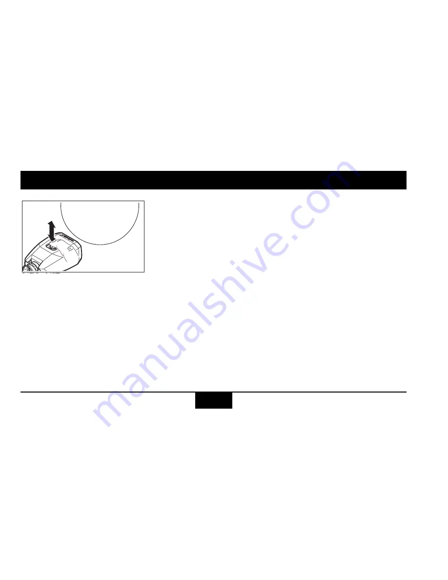
Click the button seven times
in rapid succession.
B-I-T
appears briefly, the
Built-In-Test starts auto-
matically.
Passed is indicated with
!
,
failed with
X
. In this case,
please contact the customer
support.
7x
B-I-T
B-I-T


