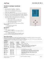
Humidistat TCY-BH-U
Doc:70-07-0102, V1.1, Date: 20100504
© Vector Controls GmbH, Switzerland
Page 11
Subject to alteration
Configuration parameters for firmware version 1.1
The TCY-BH-U can be adapted to wide variety of applications. The adaptation is done with parameters. The parameters can be
changed on the unit without the need of additional equipment.
Identifying the firmware version
The parameters and functionality of controller depend on its firmware revision. It is therefore important to use a matching
product version and parameter set. The firmware version is shown on the large LCD digits when pressing UP and DOWN
buttons for more than 3 seconds simultaneously.
Control Parameters (Access Code: 241)
Warning! Only experts should change these settings! See user parameters for login procedure.
Parameter Description
Range
Standard
CP 00
Minimum setpoint limit in humidification mode
0…100%
10%
CP 01
Maximum setpoint limit in humidification mode
0…100%
90%
CP 02
Minimum setpoint limit in de-humidification mode
0…100%
10%
CP 03
Maximum setpoint limit in de-humidification mode
0…100%
90%
Controls configuration
CP 04
Economy humidity shift
0…100%
10%
CP 05
Dead zone between humidifying & de-humidifying set point X
DZ
0…100%
10%
CP 06
Delay on humidify – de-humidify change over
0…255 min
5 min
CP 07
Switching Hysteresis
0…100%
3%
CP 08
Delay OFF (Minimum running time)
0…255s
10s
CP 09
Delay ON (Minimum stopping time)
0…255s
10s
CP 10
Configuration of control mode
0 = Both Humidification and de-humidification
1 = W04 = Humidification only
2 = W05 = De-humidification only
0 - 2
TCY-BH:
0
TCY-BH-W4: 1
TCY-BH-W5: 2
Output configuration
CP 11
Enable fan (only if CP 10
≠
0)
ON, OFF
TCY-BH:
OFF
TCY-BH-W4: ON
TCY-BH-W5: ON
CP 12
Start delay for fan
(Time the fan runs before control output starts)
0…255 s
10 s
CP 13
Stop delay for fan
(Time the fan keeps running after control output stops)
0…255 s
90 s
Temperature setback configuration
CP 14
Enable temperature setback
OFF = Temperature setback is disabled
ON = Temperature setback is enabled
ON, OFF
OFF
CP 15
Setpoint limit at full setback
0…100%
20%
CP 16
Lower temperature limit:
Outside temperature with maximum setback
The setpoint will be equal to the minimum setpoint limit
-40…60°C
-40…160°F
-30°C (-22°F)
CP 17
Upper temperature limit:
Outside temperature at begin of setback.
-40…60°C
40…160°F
0°C (32°F)
Input signal configuration
CP 18
Number of seconds taken into account to calculate the
averaging input signal.
Low value = fast response
High value = slow response
0…100 10


