

CONNECTING TO WIFI
For instructions on connecting this dimmer switch to WiFi, please see
the Supla Quick Start guide that came with the product. You will also
be able to connect to smart home systems such as Google Home and
Alexa once the Supla app has been set up.
If the Quick Start Guide has been misplaced, it can be found at
www.varilight.co.uk/leaflets
.
If you have any issues installing or using the app or creating an
account, please contact Supla for advice. Answers to FAQs can be
found here:
https://www.supla.org/en/faq
and further help can be
found at
https://forum.supla.org
.
PROGRAMMING
Programming is easily performed using the
Supla app
, with the
settings tab. This will allow you to instantly change the programming
settings with the press of a button.
The following settings can be changed with the app:
Factory Reset
Driving Mode
Boost function (for lights that don’t illuminate when turned on
at minimum brightness)
Operating range
Status LED
To get to the settings tab, select the dimmer using the Supla app, and
tap the cog in the bottom right corner (image 1). Sign in and you will be
presented with the settings screen (image 2). You can perform a
factory reset
with the circular arrow at the top. The section below this
allows you to
set modes
1, 2, or 3. Below this you can set the
Boost
on or off. The
operating range
is edited with the wheel, by moving the
dark grey squares around the wheel. The left widget is for editing the
minimum brightness, the right for the maximum. The final setting,
Status LED
, changes the behaviour of the small blue status LED
hidden behind the knob on the dimmer after the dimmer is connected
to the WiFi. The middle (default) icon sets the LED to turn on when the
WiFi connection drops. Alternatively select the icon on the left to set
the LED to stay on at all times or the icon on the right to turn it off
completely.
1. 2.
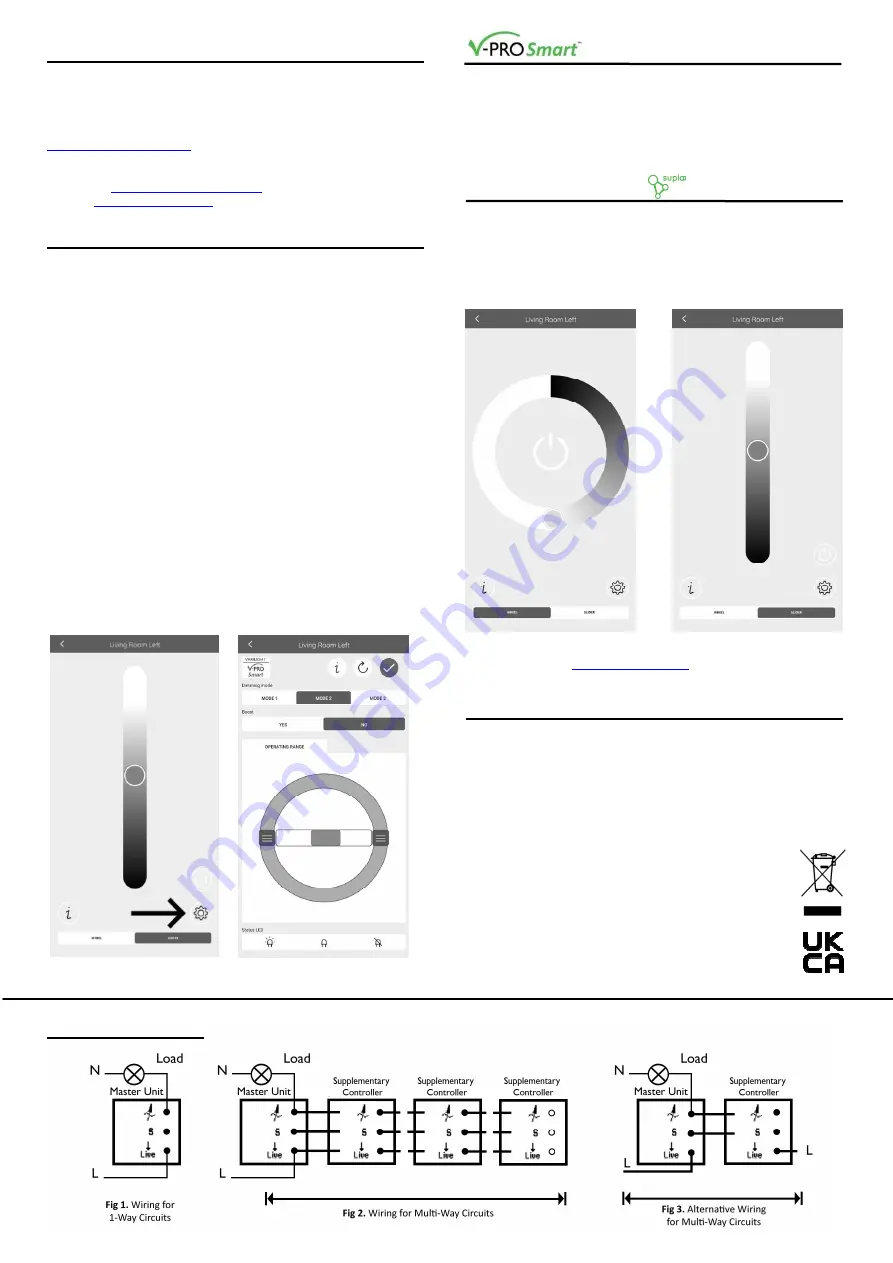
WIRING DIAGRAMS
CONTROL TIPS
There are some extra functions of this dimmer that can be used
alongside the regular push on/off and rotary dim controls.
A
sharp turn up
will set the dimmers to
maximum brightness
, with a
sharp turn down
setting them to
minimum brightness
. Either of
these can be performed from off. Turning the dimmer
slowly in either
direction
from off will bring the dimmers on at
minimum brightness
,
allowing you to ramp up from a very low level.
SUPLA APP CONTROL
To select a dimmer to control from the Supla home screen, swipe left
to bring the control screen forward. From here, there are 2 control
options at the bottom of the screen, wheel (1) or slider (2). You have
the same level of control with either, so choose whichever you prefer.
Drag the button around the wheel, or up and down the slider to dim,
and press the power button to switch on and off.
1. 2.
For extra Supla control options, including scheduling and channel
groups, please visit
https://cloud.supla.org
.
1-WAY, 2-WAY AND MULTI-WAY CIRCUITS
In 1-way lighting circuits the light(s) are controlled by one switch. This
dimmer should replace that switch. The live wire must be connected to
the terminal marked "LIVE" and the "load" wire to the terminal marked
"LOAD". To fit 2, 3 or 4-gang dimmers treat each group of terminals at
the back of the unit as a separate dimmer. You may also need a short
length of wire to connect together the "LIVE" terminals if only one live
wire is present.
For 2-way or Multi-way circuits (where the light(s) are controlled by
more than one switch) use this dimmer and any number of
V-Pro Smart supplementary controllers (total cable length
from the master to the last supplementary controller should
be no more than 50m) following the wiring diagrams below.
It is not possible to use a conventional switch in
combination with this type of dimmer. Follow the same
wiring as for 1-way circuits with three (or two) wires linking
each supplementary controller using the “LOAD” terminal,
“S-LINK” terminal and “LIVE” terminal. For more information
please refer to the wiring diagrams below.


