background image

2.5 Adjusting Homogeneity

01-999162-00  C0402

VNMR 6.1C User Guide: Solid-State NMR

30

6.

Attach the lock cable from lock preamp to the observe (OBS) connector on the 
probe.

7.

Lock the spectrometer and shim on the lock signal. The principle shims involved in 
adjusting homogeneity when a magic angle spinning (MAS) probe is used are: Z1, 
Z2, X, Y, XZ, YZ, XY, and X2Y2. 

A typical procedure is:

a.

adjust Z1, X, Y, and Z2 

b.

adjust XZ, YZ, XY, and X2Y2

c.

readjust Z1 and Z2 

d.

adjust any other off-axis shims as necessary

8.

To see how well the field homogeneity has been adjusted, do the following:

9.

Turn the lock transmitter off by entering 

lockpower=0


lockgain=0 

alock=’u’ su

10. Disconnect the lock cable from the probe.

11. Connect the cables so that the observe (OBS) port of the probe is connected to the 

observe connector on the magnet leg.

a.

Acquire a deuterium spectrum using the deuterium parameter set. The 
deuterium linewidth should be typically between 1 and 5 Hz.

b.

Finer adjustment and evaluation of the homogeneity is possible using a 
sample of solid adamantane (not available from Varian). A linewidth between 
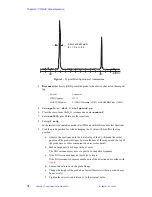
2 and 10 Hz is typically attainable, see the sample spectrum in 

Figure 5

.

A solids probe is not locked during normal operation and Z0 must be adjusted 
manually to put the lock on resonance when shimming. When the lock is on 
resonance the spectrometer will correctly set the transmitter and decoupler 
frequencies. It will be necessary to periodically reset z0 to compensate for 
magnet drift whenever you shim. Between shimming sessions it is sufficient 
to adjust 

reffrq

tof

 and 

dof

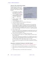
12. Continue with section 

 “Positioning the Probe and Shimming the D

2

O FID or 

Spectrum,” page 30

.

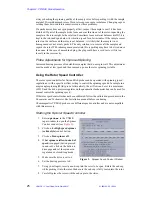
Positioning the Probe and Shimming the D

2

O FID or Spectrum 

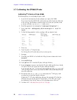
1.

Enter 

lockpower=0 lockgain=0 rtp(‘/vnmr/parlib/xpolar1’)

.

2.

Enter 

su

.

3.

Disconnect the lock cable from the probe. 

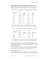
System

Connector

INOVAcpmas

J5205

MERCURYcpmas

LOCK PREAMP (J5202) or LOCK PROBE (J6002)

System

Connector

INOVAcpmas

J5311

MERCURYcpmas

LO BAND Preamp (J5302) or FROM BB Probe (J6001)

Содержание Solid-State NMR

Страница 1: ...User Guide Solid State NMR Varian NMR Spectrometer Systems With VNMR 6 1C Software Pub No 01 999162 00 Rev C0402 ...

Страница 2: ...User Guide Solid State NMR Varian NMR Spectrometer Systems With VNMR 6 1C Software Pub No 01 999162 00 Rev C0402 ...

Страница 3: ...d performance characteristics of the software described in this manual may be changed at any time without notice Varian reserves the right to make changes in any products herein to improve reliability function or design Varian does not assume any liability arising out of the application or use of any product or circuit described herein neither does it convey any license under its patent rights nor...

Страница 4: ... 3 Wideline Solids Module Operation 46 3 1 Wideline Solids Module 46 3 2 Wideline Experiments 50 3 3 SSECHO Pulse Sequence 51 3 4 Data Acquisition 51 3 5 Standard Wideline Samples 53 3 6 Data Processing 55 Chapter 4 CRAMPS Multipulse Module Operation 56 4 1 Introduction to Multipulse Experiments 56 4 2 CRAMPS Multipulse Module Hardware 57 4 3 Multipulse Experiments and User Library 60 4 4 Multipul...

Страница 5: ...iting 98 6 12 3QMAS1 Triple Quantum 2D for Quadrupole Nuclei 99 6 13 PASS1 2D Sideband Separation for CP MAS 101 6 14 CPCS Cross Polarization with Proton Chemical Shift Selection 102 6 15 CPCOSYPS Cross Polarization Phase Sensitive COSY 103 6 16 CPNOESYPS Cross Polarization Phase Sensitive NOESY 104 6 17 R2SELPULS1 Rotation Resonance with Selective Inversion 106 6 18 DIPSHFT1 Separated Local Field...

Страница 6: ...ids Cabinet Layout Open Front View 48 Figure 17 Real Channel FID Pattern 62 Figure 18 FLIPFLIP FID at Exact 90 Pulse 62 Figure 19 FLIPFLOP Tram Tracks 63 Figure 20 FLIPFLOP Desired FID 63 Figure 21 Adipic Acid Spectrum 65 Figure 22 Pulse Sequence for flipflop c 68 Figure 23 BR24 Pulse Sequence 69 Figure 24 MREV8 Pulse Sequence 70 Figure 25 WaHuHa Pulse Sequence 71 Figure 26 Pneumatics Tachometer B...

Страница 7: ...120 Figure 55 HS90 Pulse Sequence 121 Figure 56 MREVCS Pulse Sequence 122 Figure 57 MQ_SOLIDS Pulse Sequence 123 Figure 58 SPINDIFF Pulse Sequence 124 Figure 59 FASTACQ Pulse Sequence 125 Figure 60 NUTATE Pulse Sequence 126 List of Tables Table 1 Background Nuclei of Rotor Material 19 Table 2 Typical Spin Rates with Associated Bearing and Drive Values 21 Table 3 Reference Materials and 13 C Chemic...

Страница 8: ...sthetic parts and metal blood vessel clips and clamps Pacemaker wearers should consult the user manual provided by the pacemaker manufacturer or contact the pacemaker manufacturer to determine the effect on a specific pacemaker Pacemaker wearers should also always notify their physician and discuss the health risks of being in proximity to magnetic fields Wearers of metal prosthetics and implants ...

Страница 9: ...plosion or fire WARNING Leave area immediately in the event of a magnet quench If the magnet dewar should quench sudden appearance of gasses from the top of the dewar leave the area immediately Sudden release of helium or nitrogen gases can rapidly displace oxygen in an enclosed space creating a possibility of asphyxiation Do not return until the oxygen level returns to normal WARNING Avoid helium...

Страница 10: ...nets only the dewar includes removable helium vent tubes If the magnet dewar should quench sudden appearance of gases from the top of the dewar and the vent tubes are not in place the helium gas would be partially vented sideways possibly injuring the skin and eyes of personnel beside the magnet During helium servicing when the tubes must be removed follow carefully the instructions and safety pre...

Страница 11: ...will destroy liquids probes Use the appropriate high power probe with the high power amplifier CAUTION Take electrostatic discharge ESD precautions to avoid damage to sensitive electronic components Wear grounded antistatic wristband or equivalent before touching any parts inside the doors and covers of the spectrometer system Also take ESD precautions when working near the exposed cable connector...

Страница 12: ... the etc directory The same type of characters show text displayed on the screen including the text echoed on the screen as you enter commands during a procedure For example Self test completed successfully Text shown between angled brackets in a syntax entry is optional For example if the syntax is seqgen s2pul c entering the c suffix is optional and typing seqgen s2pul c or seqgen s2pul is funct...

Страница 13: ...ian NMR Spectrometer Systems In parts of this manual the type of spectrometer system UNITY INOVA MERCURY VX MERCURY GEMINI 2000 UNITYplus UNITY or VXR S must be considered in order to use the software properly UNITYINOVA and MERCURY VX are the current systems sold by Varian UNITYplus UNITY and VXR S are spectrometer lines that preceded the UNITYINOVA MERCURY and GEMINI 2000 are spectrometer lines ...

Страница 14: ...pplied at the proton resonance frequency A second cause of line broadening in polycrystalline compounds is chemical shift anisotropy CSA This is the result of nuclei with different orientations in the applied magnetic field resonating at different Larmor frequencies The observed spread of the chemical shifts is called the chemical shift anisotropy and can be as large as a few hundred ppm This inte...

Страница 15: ...ng the cross polarization experiment for quantitative analysis 1 3 Solids Modules Probes and Accessories Varian supplies a complete line of solid state NMR modules probes and accessories Solids modules include CP MAS wideline CRAMPS multipulse and complete solids CP MAS wideline and CRAMPS Multipulse hardware and operation are covered in Chapters 2 3 and 4 respectively of this manual The Varian co...

Страница 16: ... containing one or more 1 kW amplifiers MERCURYplus and MERCURY Vx systems with the 100 300 CP MAS option CP MAS Hardware for 100 300 Watt Systems The CP MAS option is available for most narrow bore UNITY and all UNITY INOVA UNITYplus MERCURYplus and MERCURY Vx systems A class A B AMT 3900A 15 linear amplifier with a maximum output of 100 W for up to 250 ms replaces the standard 1 H 19 F liquids l...

Страница 17: ...n the parameter ampmode is not present the amplifier is set in the default CW mode ampmode c or d which is correct for CP MAS experiments CMA amplifier modes CLASS C CLASS AB CW or GATE ACTIVE pulsed are selected using the three position switch on the front panel of the amplifier Set the switch to CLASS AB mode for CP MAS experiments GATE ACTIVE mode for 1 H or 19 F observe or CLASS C for special ...

Страница 18: ... in voltage or field strength is linear and quadratic in power The attenuator control in dB is shown in Figure 1 A rough rule is for a 2 fold change in fine power there is a 6 db change in the coarse power tpwr or dpwr Power is controlled using the parameters tpwrf dpwrf dpwrf2 and dpwrf3 Aliases of these parameters ending in m rather than f are used in some pulse sequences including XPOLAR1 The p...

Страница 19: ...MAS rotors for all systems A manual box allows adjustment of bearing and drive pressure with knobs and is independent of the console Alternatively a rotor speed controller is available for UNITY INOVA and all MERCURY systems with the solid option Rotor speed control is obtained by modulation of the drive flow and is under computer control The Rotor Speed Controller tachometer box is distinguished ...

Страница 20: ... differential contraction with the ceramic rotor exists Kel F end caps colorless opaque have a VT upper limit of about 70 C and should not be spun faster than 6500 Hz at any temperature Use pMMA colorless clear end caps only at room temperature and below Visually distinguishing between Kel F and pMMA end caps can be difficult so you may want to mark them appropriately Table 1 Characteristics of Va...

Страница 21: ...ials to 0 440 0 005 in 11 176 mm in length with a diameter of 0 1960 0 0005 in 4 979 mm for Varian 7 mm rotors or 0 137 in 3 48 mm for Varian 5 mm rotors and placed inside a rotor Granular and Powdered Materials The best method for filling the rotors with granular or powder materials is to pour the material into the rotor and leave just enough room for the cap Granular and powdered materials work ...

Страница 22: ...n faster then liquid samples Care must be used in filling the rotor to avoid lubricating the end cap with the sample If the end cap is lubricated with the sample the cap could pop off during the experiment A very small dot of cyanoacrylic glue can be used to secure the end cap Do not use to much glue or you will not be able to remove the end cap later 2 4 Spinning the Sample WARNING A projectile h...

Страница 23: ...t is installed on your system Pneumatics tachometer box with rotor spin speed control from within VNMR see Using the Rotor Speed Controller page 25 Pneumatics tachometer box with manual spin control see Using the Manual Pneumatics Tachometer Box page 28 Centrifugal force can cause the black and white markings to flake off around the edges This can cause inaccurate tachometer readings The black or ...

Страница 24: ...sed by the sample material A damaged rotor might be at fault but that can be eliminated by Table 3 Typical 7 mm CP MAS Probe Spin Rates With Bearing and Drive Values Rates are approximate values for the Varian 7 mm CP MAS probe at ambient temperature The actual spin rate will vary depending on the properties of the sample and sample holder Spinning Speed Hz 250 Hz Bearing Drive Pressure psig bar F...

Страница 25: ...ed up once the rotor spinning is stable Using the Rotor Speed Controller The rotor speed controller for Varian MAS probes can be operated with spinning speed regulation or with a specific airflow setting to control the spinning speed of a sample in a magic angle spinning MAS probe Alternatively the air flow can be set to a maximum 65535 and the drive pressure regulator on the pneumatics tachometer...

Страница 26: ...ner should regulate to 2 Hz or better within about 30 seconds to 1 minute 2 Experiment with a number of set points within the rated speeds of the sample rotor and probe 3 Set the desired spin speed using the slider bar Regulating Spinning Speed within VNMR This procedure describes how to regulate spinning speed by entering commands in the VNMR input window 1 Start the rotor speed controller as des...

Страница 27: ...no spin speed regulation 8 Set the slider bar at 2500 9 If the rotor fails to spin or no DAC reading appears on the tachometer stop the rotor and remove it from the probe check the paint on the rotor and the tachometer cables Repeat this procedure beginning at step 1 10 Adjust the slider bar until the rotor is spinning at the desired speed Move the slider bar slowly If the rotor is spinning changi...

Страница 28: ...he end cap while pushing it into the rotor Make sure the end cap is fully seated into the rotor 2 Make sure the bearing and drive air pressure are off 3 Carefully place the rotor with the end cap into the stator and install the probe into the magnet Turn the air bearing pressure to 28 psig 2 0 bar the rotor should start spinning slowly at 500 900 Hz 4 Slowly turn on the air drive pressure to 3 6 p...

Страница 29: ...r each experiment to show the spinning speed Furthermore if in y an acquisition is halted if the spinning speed differs by more than 100 Hz from spinning speed at the start of the acquisition For further details on rotor synchronization refer to the manual System Operation 2 5 Adjusting Homogeneity For the balance of this manual MERCURYcpmas will refer to MERCURY Vx and MERCURYplus systems equippe...

Страница 30: ...h should be typically between 1 and 5 Hz b Finer adjustment and evaluation of the homogeneity is possible using a sample of solid adamantane not available from Varian A linewidth between 2 and 10 Hz is typically attainable see the sample spectrum in Figure 5 A solids probe is not locked during normal operation and Z0 must be adjusted manually to put the lock on resonance when shimming When the loc...

Страница 31: ... shim and the initial position of the probe distance between the base of the magnet and the top of the probe base or other convenient fixed reverence point b Make a large positive change in the z1 shim The D2O resonance may move to positive or negative frequency c If the D2O resonance does not move go to step h If the D2O resonance does move make note of the direction and continue with step d d Lo...

Страница 32: ...isotropy CSA pattern For carbons with significant anisotropy such as aromatics and carbonyls this can greatly affect the linewidth of the observed resonance In general once adjusted the magic angle should stay fairly constant However this is not guaranteed The angle should be checked and adjusted as follows When the probe is inserted in the magnet Every few days of continuing operation If linewidt...

Страница 33: ...e spikes on it see Figure 7 and Figure 8 If the signal is not exactly on resonance repeat step 10 and step 12 15 Select IPA and adjust phfid to maximize the on resonance FID 16 Adjust the angle using the fiberglass rod with the adjustment tool Maximize the size and number of spikes in the picket fence The spikes should persist for about 10 ms The sample angle is now set to the magic angle 17 Close...

Страница 34: ...R 6 1C User Guide Solid State NMR 34 Figure 7 FID Display of KBr on Angle Figure 8 FID Display of KBr 1 2 Turn Off Angle Figure 9 Typical Hexamethylbenzene HMB Spectrum 20 0 20 40 60 80 100 120 140 160 180 200 ppm HMB Aromatic Carbons HMB Methyl Carbons ...

Страница 35: ... Hz on low field side of the p dioxane resonance and enter movetof 9 Enter sw 5000 ga 10 Array pw from 0 to 5 times the 90o pulse width specification 11 Increase tpwrm as necessary to achieve the 90o pulse width specification or desired 90o pulse width Do not exceed the 90o pulse width specification If you cannot achieve the 13 C 90o pulse width specification with tpwrm set to full value you may n...

Страница 36: ...the γB2CP 1 H cross polarization field a γB2CP 1 0 4 0 13 Cpw90 where 13 Cpw90 is the value determined in the previous section b Adjust dipolr and enter ga c Repeat step 6 and 7 d Adjust the value of dipolr until the value for γB2 measured in 7 equals the value calculated in step 8a e Record the values of dipolr and γB2CP These values will be used in the next section 10 Continue with Adjusting the...

Страница 37: ...ue of tpwrm from Adjusting the Hartmann Hahn Match page 36 2 Enter d1 5 nt 4 3 Enter ga 4 Set delta 10000 and place cursor at the right edge of the spectrum and enter dnsmax to measure the signal to noise 5 Compare the signal to noise to the specifications If necessary increase the gain and repeat step 2 through step 4 Do not overload the ADC 6 Repeat step 2 and step 4 three times and record the s...

Страница 38: ...requency of re referencing depends upon the drift rate of your magnet A drift rate of 10 Hz per hour is 2 5 Hz per hour for 13 C A typical 13 C linewidth of a solid is between 30 Hz and 300 Hz For most purposes this procedure should be followed only at the time the probe is installed The 13 C chemical shifts of a few reference materials are given in Table 5 2 9 XPOLAR1 Cross Polarization XPOLAR1 i...

Страница 39: ...lus the macro XPOLAR1 will convert parameters contained in experiments run on UNITYINOVA UNITYplus and UNITY when these data sets are loaded on the system and the macro is run For users familiar with UNITY INOVA UNITYplus and UNITY solids note the following If the UNITY power parameters are defined in an XPOLAR parameter set they are converted to the corresponding UNITYINOVA and UNITYplus paramete...

Страница 40: ...field strength in kHz and halves the initial proton 90 pulse p180 greater than 0 0 implements an additional prepulse followed by a delay d2 For direct polarization xpol n p180 is an observe pulse For cross polarization xpol y p180 is a proton pulse p180 is in microseconds pcrho greater than 0 0 implements an additional observe pulse following the contact time Use pcrho for observe T1ρ measurements...

Страница 41: ...ily occur A value of 1000 µs is adequate for protonated carbons and crystalline solids A value of 3000 µs is needed for non protonated carbons and solids with internal motion Optimizing the Repetition Rate Acquisition times in CP MAS spectra are determined by the desired spectral resolution Typically set sw 50kHz With at 0 05 this gives at least 2048 data points and a digital resolution of 4 Hz a ...

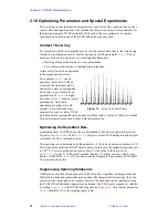
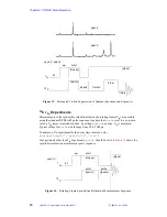
Страница 42: ...hat is used in solids to discriminate between carbon types and that is the protonated carbon suppression experiment of Opella and Fry In this experiment the decoupler is turned off for 40 to 100 µs before acquisition to dephase the protonated carbons The technique is effective primarily for non mobile carbons mobile carbons like methyl groups are typically not suppressed as well Figure 13 shows a ...

Страница 43: ...lues for pcrho would range from 50 to 5000 µs To analyze a Tlρ experiment for the decay time constant enter analyze expfit pcrho t2 list In experiments other than Tlρ experiments pcrho should be set to 0 Figure 14 shows the spin lattice relaxation measurement pulse sequence pdp n pdp y Figure 13 Protonated Carbon Suppression of Alanine Spectrum and Sequence 13 C 1 H dipolr xpol y pdp y d1 pw cross...

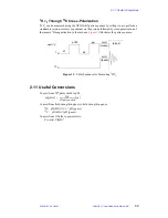
Страница 44: ...owed by cross polarization of the remain 1 H magnetization to the carbons Figure 15 illustrates the pulse sequence 2 11 Useful Conversions Convert from 90 pulse width to γH Convert from field strength in gauss to field strength in gauss 1H γH kHz 4 3 γH gauss 13 C γH kHz γH gauss Convert from rf fields to power levels P watts γH 2 Figure 15 Pulse Sequence for Measuring l H T1 13 C xpol y 1H cntct ...

Страница 45: ...Chapter 2 CP MAS Solids Operation 45 VNMR 6 1C User Guide Solid State NMR 01 999162 00 C0402 ...

Страница 46: ...sed often greatly exceed the linewidths because many spectra are obtained under over digitized conditions 3 1 Wideline Solids Module The wideline module for the Varian spectrometer modifies and extends the basic capability of the system in a number of areas The main components of the wideline module are the wideband ADC high power amplifier and the solids cabinet Wideline ADC Board A wideline anal...

Страница 47: ...are routed to the wideband ADCs The permissible values of the parameter fb which are identical to the 3 dB points of these filters are listed in Table 6 For 100 kHz and below the signal is routed through a pair of 8 pole quasi elliptical filters to standard ADCs The characteristics of these filters provide superior performance for both phase and amplitude flatness across the full spectral width Th...

Страница 48: ...ance for this delay must be made in any pulse sequence programming using rof1 The amplifier can be driven in either of two modes Continuous wave CW the maximum power output is limited to 200 W but the duty cycle can be 100 Pulsed the maximum power output is 1 kW but the maximum pulse width is 8 ms with a maximum duty cycle of 10 The amplifier is fully protected against thermal overload excessive d...

Страница 49: ...at 100 MHz so that when its front panel gain control is set to the marked position and the manual attenuators are set to 0 the power output is equal in dBm to the value of tpwr in other words tpwr 60 delivers 1 kW 60 dBm and tpwr 50 delivers 100 W 50 dBm This calibration may not be precise at other frequencies but provides a first approximation AMT Linear Amplifier The AMT linear amplifier is gate...

Страница 50: ... high power 1 kW amplifier HI POWER position 3 2 Wideline Experiments Wideline NMR experiments can be divided into three main areas based on spin quantum number I The experiments possible are certainly not restricted to just one of these categories but are normally used in one group rather than in all Table 7 lists commands and parameters related to wideline experiments Dipolar Nuclei I 1 2 The mo...

Страница 51: ...e also observed via echo sequences however as different types of lineshape information may be sought a number of different echo sequences may be used depending on the quantum transitions of interest I D Weisman and L H Bennett Phys Rev 181 1344 1969 3 3 SSECHO Pulse Sequence One basic pulse sequence SSECHO is provided to support quadrupolar wideline experiments This pulse sequence can perform conv...

Страница 52: ...mportant shims Usually it is only important to adjust X Y Z1 Coarse and Z2 Coarse 4 When finished shimming turn the lock off and adjust Z0 so that the lock signal is on resonance This ensures that the field will be in the same position as used for liquids work so that the usable frequencies will be the same 5 Set lpower 0 This ensures that at the time of the next su command the lock transmitter is...

Страница 53: ...be as described in the probe installation manual 4 Now instead of the observe channel connect the lock channel to the probe Lock the spectrometer in the usual way The spectrometer can now be shimmed using acqi but there is no point trying to obtain a resolution that is markedly better than the lines to be observed so that only the gradients X Y Z1 Coarse and Z2 Coarse need be optimized 5 Make sure...

Страница 54: ...a Other spectra can now be acquired using these parameters Obtaining a Wideline Spectrum of 23 Na Sodium does not normally have a parameter set in stdpar so it is necessary to call up some standard set and modify it The easiest way to do this is shown in step 1 below 1 Enter setup H2 d2o tn Na23 dm n su 2 Set up the probe with the correct coil and tuning rod if any and put in a sealed sample of Na...

Страница 55: ...eft shift of the FID may be used to shift the FID until the echo occurs at the first point of the FID Normally the echo top is well enough defined so that left shifting removes all distortion However this is not always the case especially with very short T2 echoes A means of fractionally left shifting has been provided as follows lsfid n phfid n ft ft inverse n expn jexpn scalesw 1 0 n df wft In t...

Страница 56: ...mbined Rotation and Multipulse CRAMPS is the most common 1 H high resolution experiment CRAMPS is used to obtain high resolution MAS 1 H spectra of organic materials The CRAMPS pulse sequence uses the BR24 multiple pulse cycle A BR24 multiple pulse cycle applies 24 1 H 90o pulses in the dwell time between the acquisition of complex data points Multiple pulse cycles such as BR24 removes strong 1 H ...

Страница 57: ...tuned to either 1 H or 19 F At 600 MHz only 1 H tuning is possible INPUT TUNING uses the 20 turn pot at the front of the amplifier chassis The output tuning uses the external Motor Control Box A 3 position selector switch is used to choose TUNE LOAD and STANDBY AUX The COARSE and FINE toggles are momentary contact and can be pushed in two directions designated IN and OUT to adjust either the TUNE ...

Страница 58: ...s after the pulse For 1 H CRAMPS the noise and RF ring down over a period of about 2 0 3 0 µs before detection of a data point is possible During this period the T R switch if present see Solids Preamplifiers below immediately gates to receive mode and then after a delay a trigger is sent to turn the receiver on When using the fast ADC the receiver then turns on within about 1 0 µs The delay betwe...

Страница 59: ...m standard 1 H 19 F module Check the part numbers and instrument documentation if there is any doubt about an existing preamp Set rof2 0 5 µs Other preamplifiers are not suitable for CRAMPS and cannot be in line during CP MAS decoupling Ring down of these preamps may be too long or the diodes may not withstand the RF duty cycle MAS Probes for CRAMPS Any CP MAS probe with a 1 H decoupler channel ca...

Страница 60: ...nt to shorten T1 2 Center the bulb in the coil Alternatively a small solids sample of RTV silicon rubber caulk from the hardware store will provide a 1 H linewidth sufficient for tuning Spin the RTV at about 2 kHz during these measurements User Library Terms and Conditions Material submitted to the user library is distributed by Varian as a service to its users All rights to the material submitted...

Страница 61: ...to place the signal on resonance with tof 0 0 Be sure the receiver gain is low so as to avoid overload gain 20 and d1 is set to insure full recovery of the signal Calibrate the Exact 90o Pulse Width FLIPFLIP or XX This procedure is accomplished by retuning the probe or amplifier while observing a repeating cycle of alternating X and X pulses The procedures for tune up are as follows 1 Enter the ma...

Страница 62: ... should appear similar to Figure 17 or Figure 18 4 Type gf and then acqi 5 Press the FID button and then press again to select the FID display 6 Press IPA and adjust the tpwrf slider to achieve a display similar to Figure 18 The ideal signal pattern 1 0 0 0 1 0 0 0 N results from a 90o pulse The bulge among the first few zero points and the decay are due to RF inhomogeneity A distribution of pw90 ...

Страница 63: ...esonance to correctly run X X 3 Adjust the system tuning see System Tuning page 63 to remove the curvature of Figure 19 and obtain a result similar to Figure 20 System Tuning The ideal signal pattern is 1 0 0 0 N Curvature similar to Figure 19 results from phase transient or phase glitch Phase transient is a small shift f t in phase during the rise and fall times of the pulse Asymmetric phase tran...

Страница 64: ...orrect d1 1 0 with a relaxation agent Set trig n trig y for UNITY and VXR S with a Sync Module 8 Array tof in 1 kHz steps form 1e4 to 1e4 9 Type ga The resulting display should show a single resonance that moves with tof Measure the frequency shift of the resonance with each change in offset This value divided by 1000 is the experimental multiple pulse scale factor S S will probably be offset depe...

Страница 65: ...reference this line at 2 0 ppm c The chemical shift scale and reference are now correct and an additional line should be present at 13 to 14 ppm 17 Run the experimental sample with the same data set and tuning 4 6 How to Obtain Good CRAMPS Spectra MREV8 and BR24 pulse sequences must be used with slow spinning so that the length of a rotor cycle tr greater than one multiple pulse cycle tauc Interfe...

Страница 66: ...anty Use as short a 90o pulse that you feel is safe for a given probe The quality of a CRAMPS spectrum is improved by shortening the interpulse spacing tau The lower limit for tau is determined by the time required to collect the data point during one of the 2 tau periods of the pulse sequence The recommended tau 3 5 µs provides a 5 5 µs window to collect a data point when pw 1 5 µs Smaller values...

Страница 67: ... set sw equal to the spin rate to eliminate any sidebands In contrast multipulse methods must use open analog filters to avoid pulse ring down and folded noise from the full receiver bandwidth 2 5 MHz lowers the signal to noise One multipulse sequence WaHuHaHS can be used with fast MAS spinning WaHuHaHS is a semi windowless version of the original multipulse sequence WaHuHa Both sequences have a f...

Страница 68: ...d 2 x for FLIPFLOP trig y for UNITY and VXR S with a Sync Module Otherwise trig n np is the number points and np 128 or 256 tau is interpulse delay in microseconds including pw The minimum tau is about 7 0 µs when pw 1 5 µs See rof1 and rof2 rof1 is the amplifier unblanking time before each pulse The receiver is also immediately blanked and a T R switch if present is placed in transmit mode Set ro...

Страница 69: ...olled by the parameter phase1 To minimize the pedestal p1 should be set to the 90o flip angle and phase1 135 tau is the interpulse delay in microseconds including pw The BR24 cycle is 36 tau long and is repeated np 2 times to build up a FID trig y for UNITY and VXR S with a Sync Module Otherwise trig n tauc is the cycle time in microseconds and is the actual dwell time for the FID tauc is not chan...

Страница 70: ...ength in microseconds tau is the interpulse delay in microseconds including pw The MREV8 cycle is 12 tau long and is repeated np 2 times to build up a FID trig y for UNITY and VXR S with a Sync Module Otherwise trig n tauc is the cycle time in microseconds and is the actual dwell time for the FID tauc is not changed and is for information only mp_at is the sum of all cycles in microseconds and is ...

Страница 71: ...gth in microseconds tau is the interpulse delay in microseconds including pw The WaHuHa cycle is 6 tau long and the WaHuHaHS is 4 tau 2 pw They are repeated np 2 times to build up a FID tauc is the cycle time in microseconds and is the actual dwell time for the FID tauc is not changed and is for information only mp_at is the sum of all cycles in microseconds and is the true acquisition time mp_at ...

Страница 72: ... a convenient position The four hoses coming out of the left side of the pneumatics box are connected to the probe ROTATION DRIVE BEARING BODY GAS and the EJECT port of the magnet These connectors are of a high pressure quick disconnect type 5 2 Rotor Synchronization Operation In a number of experiments it is desirable to trigger an event at a precise point in the rotation period of a rotor Usuall...

Страница 73: ...otor edge delaying n edges and then counting the counter down to zero At this point the delay is finished Thus in principle the error in the delay will be only that percentage that the first and the last periods differ This is shown as mode 3 in Figure 27 A potential source of error exists in determining the point of the light transition on which to trigger the digital circuitry This is a factor d...

Страница 74: ... for the rotor synchronization accessory depend on both the probe and the electronics The values given below reflect those that can be obtained in optimum circumstances and as such do not imply a guarantee of performance If performance is severely degraded from these values the first remedy is to check the sector markings on the rotor because any lack of definition here will have profound effects ...

Страница 75: ...rmal way The rotor is spun in accordance with the instructions in Spinning the Sample page 22 and the spinning speed may be read on the tachometer box LCD display Note that for Varian probes the optical fibers should be plugged into the tachometer box and for Doty probes the probe should be connected to the Doty tachometer amplifier the switch on the amplifier set away from the OPTICAL OFF positio...

Страница 76: ...tically compensated Rotor Speed Controller Hardware The rotor speed controller accessory consists of the following hardware Modified Varian VT pneumatics tachometer box PC compatible computer with 16 bit timer counter and DAC cards Cabling to connect PC pneumatics tachometer box and Sun workstation The use of a PC computer provides an inexpensive powerful and dedicated processor for rotor speed co...

Страница 77: ...session and confirmation by the user Configuration Routines The configuration F choice at the main menu displays the current gain settings used in the closed loop control process and allows you to change them Besides the gain values the configuration routines allow you to set the following Loop delay set in milliseconds Increment clamp value for the loop increment The loop delay specifies a time d...

Страница 78: ... extended periods of time weeks or months If the CMOS does lose its memory settings a video card PC monitor and keyboard will have to be attached so that the CMOS set up program not part of DOS can be run 5 4 Variable Temperature Operation with Solids This section provides general instructions on the solids variable temperature VT accessory The accessory installation manual for the system provides...

Страница 79: ... Connect the VT gas supply to the probes is made as described in the Doty manual The VT controller is connected to the boost supply and the boost supply is connected to the probe The liquids upper barrel is pushed down so it touches the top of the probe The upper barrel then acts as an exhaust stack VT operation requires Vespel end caps Vespel is less susceptible to thermal deformation at high tem...

Страница 80: ... 6 14 CPCS Cross Polarization with Proton Chemical Shift Selection page 102 6 15 CPCOSYPS Cross Polarization Phase Sensitive COSY page 103 6 16 CPNOESYPS Cross Polarization Phase Sensitive NOESY page 104 6 17 R2SELPULS1 Rotation Resonance with Selective Inversion page 106 6 18 DIPSHFT1 Separated Local Field Spectroscopy page 108 6 19 SEDRA2 Simple Excitation of Dephasing Rotational Echo Amplitudes...

Страница 81: ...tion is then transferred to the rare spins by applying an rf field at the Larmor frequency of the rare spins that is of such magnitude as to make the energy levels of the abundant and rare spins the same in the rotating frame the Hartmann Hahn match condition Following a transfer of energy from the polarized spins to the rare spins the rare spin field is turned off and resulting signal observed un...

Страница 82: ...based on the parameter pw It may be necessary to adjust pw to optimize the TOSS experiment Figure 30 shows the pulse sequence diagram for cross polarization with TOSS Suppression of Protonated Carbons Interrupted Decoupling Off resonance decoupling and related experiments such as DEPT in which J coupling is involved are not usually possible in solids because through space dipolar coupling as well ...

Страница 83: ...ent experiment analyze inp is generated by a line listing of the peaks of interest in a spectrum and by the fp command which measures the peak height of each peak in an array of spectra The second argument of analyze is the name of the arrayed parameter which in the case of 13 C T1ρ experiments using the xpolar sequence is the parameter p3 for xpolar1 use pchro The third argument is the type of an...

Страница 84: ...set to a 180 inversion pulse or the initial proton pulse usually set to a 180 pulse cross polarization p1 is in microseconds p2 is the cross polarization contact time in microseconds p3 is a pulse in microseconds for an X nucleus only spin lock following p2 dm should be set to nny The decoupler has a maximum duty cycle of 20 d2 is delay between p1 and pw for inversion recovery if pdp n If pdp y d2...

Страница 85: ...J S J Chem Phys 1973 59 569 Stejskal E O Schaefer J Waugh J S J Magn Reson 1977 28 105 Spinning Sidebands Herzfeld J Berger A E J Chem Phys 1980 73 6021 Dixon W T J Magn Reson 1981 44 220 Dixon W T J Magn Reson 1982 49 341 Dixon W T J Magn Reson 1985 64 332 Protonated Carbon Suppression Opella S J Fry M H J Am Chem Soc 1979 101 5856 Relaxation Times Schaefer J Stejskal E O Buchdahl R Macromolecule...

Страница 86: ...s the macro XPOLAR1 will convert parameters contained in experiments run on UNITYINOVA UNITYplus and UNITY when these data sets are loaded on the system and the macro is run For users familiar with UNITY INOVA UNITYplus and UNITY solids note the following If the UNITY power parameters are defined in an XPOLAR parameter set they are converted to the corresponding UNITYINOVA and UNITYplus parameters...

Страница 87: ...pulse followed by a delay d2 For direct polarization xpol n p180 is an observe pulse For cross polarization xpol y p180 is a proton pulse p180 is in microseconds pcrho greater than 0 0 implements an additional observe pulse following the contact time Use pcrho for observe T1ρ measurements The units for pcrho are microseconds dm should be set to nny The decoupler has a maximum duty cycle of 20 pdp ...

Страница 88: ...he observe 90 pulse length pwx follows the contact time and when set to 90 rotates the observe magnetization to the minus z axis and nulls the NMR signal Array pwx between the 0 and 360 pulse The first null is the observe 90 pulse The signal is negative for 180 null for 270 and positive for 360 When the Hartmann Hahn condition is matched for a non spinning sample the proton 90 pulse pw equals pwx ...

Страница 89: ...peaks appear when self or chemical exchange occurs Figure 36 is a diagram of the sequence Macro The xnoesysync macro sets up parameters for the XNOESYSYNC pulse sequence Parameters pw is the 1 H 90 pulse in microseconds for cross polarization p2 is the contact time in microseconds d2 is the evolution time in seconds dm is set to nny for no proton decoupling during the mixing time or dm is set to n...

Страница 90: ... M Veeman W S Chem Phys Lett 1984 109 337 6 5 MASEXCH1 Phase Sensitive Rotor Sync Sequence for Exchange MASEXCH1 is a rotor synchronized CP MAS exchange sequence similar to XNOESYSYNC except that this sequence can yield a phase sensitive spectrum rather than an absolute value plot This experiment should be run under slow spinning conditions since spinning sidebands intensities carry the informatio...

Страница 91: ...o the reference for transformation with wft2d 1 0 0 1 1 0 0 1 0 1 1 0 0 1 1 0 The phase sensitive spectrum is the sum of a Veeman experiment phase 1 2 and a time reversed experiment phase 3 4 mix is the mixing time in seconds For phase 1 2 3 4 the minimum mixing time is equal to ni 1 sw1 For phase 1 2 the minimum mixing time is 0 0 sync y to run with rotor synchronization sync n to run unsynchroni...

Страница 92: ...mal operation Set setup y to obtain a single t1 FID blew is the number of BLEW 12 cycles You may use setup set to y to obtain a one dimensional spectrum using a proton chemical shift selection pulse or to observe the pulse sequence with dps for ni greater than 1 pw is both the 1 H 90 pulse and the 13 C 90 pulse the pulses must be equal Adjust tpwrm using xpwxcal to make the pulse lengths equal wim...

Страница 93: ...andard digitizer For WISE1 sw1 can be set in excess of 100 kHz The macro wise1 converts a parameter set obtained with XPOLAR or XPOLAR1 for the WISE experiment Power levels and proton 90 pulse width are retained Default parameters set up for WISE with no mix period and a 200 kHz spectral width Applicability WISE1 is available for UNITYplus and UNITYINOVA systems and can be found in SolidsLib versi...

Страница 94: ... to obtain programmed decoupling during acquisition and set to c for continuous decoupling For dmm c the wfg parameters are hidden dmf is the decoupler modulation frequency and is set equal to one over four times the decoupler 90 pulse dmf must be calibrated and depends upon the value of dipolr The macro makes an estimate as described above Calibrate dipolr with a sample of dioxane and the macro h...

Страница 95: ...ing speeds These two sequences provide access to a variety of the phase frequency and amplitude modulated CP methods in the literature Two macros xmodcos and xmodramp create specific amplitude modulated cosine and ramped waveform DEC files This sequence requires a waveform generator on the appropriate channel X or H Without a waveform generator or for general purposes use VACP instead Figure 38 is...

Страница 96: ...0 2 microseconds dmf and dres are not used to control the cross polarization waveform You can also set programmed decoupling during acquisition by the usual procedure using dmf and dres xmodcos frac per amp creates a waveform with the following function amp 1 0 frac 2 0 frac 2 0 cos t per where t is time The resulting DEC file has the form xmodcos_frac_per_amp DEC where frac is x10000 and per is i...

Страница 97: ...in removing the spinning speed dependence of cross polarization In the VACP sequence during the contact time 1 H power is varied among 11 levels with the appropriate amplitudes The difference between the maximum and minimum values of γB2 in Hz should be at least twice the maximum rotor speed to be used Figure 39 is a diagram of the VACP sequence Applicability VACP is available on UNITYINOVA UNITYp...

Страница 98: ...s for spectral editing of CH3 CH2 CH and C carbons by use of differences in their cross polarization properties The sequence provides a 180 phase shift during the contact time depolarization followed by a return to the original phase repolarization Individual carbon types can be nulled with appropriate delays p3 and p4 and spectral editing can be achieved by addition and subtraction of subspectra ...

Страница 99: ...are field dependent The lineshape in the f2 dimension is similar to that obtained with MAS alone Because resonances are resolved in f1 the lineshapes are easily simulated individually with a general simulation program such as STARS The shift in f1 and the lineshape in f2 are related and provide redundant information about quadrupole and chemical shift tensor components Figure 41 is a diagram of th...

Страница 100: ... it to single quantum coherence pulse 2 for detection The default is pw3q 2 pw Set pw3q to a larger value e g pw3q 8 pw for greater triple quantum signal to noise in some cases tpwr is the observe coarse attenuator setting for pulses 1 and 2 tpwrm is the observe linear modulator setting for pulses 1 and 2 tpwrs is the observe coarse attenuator setting for the selective refocusing pulse pulse 3 The...

Страница 101: ... plot with an isotropic spectrum in f1 and a MAS sideband pattern in f2 There is negligible loss of signal intensity Chemical shift tensor components can be determined from the sideband intensities in f2 Figure 42 is a diagram of the PASS1 sequence Applicability PASS1 is available on UNITY INOVA and UNITYplus and present in userlib Macro The macro pass1 converts a parameter set obtained with XPOLA...

Страница 102: ...m 16 to obtain a manifold of 16 sidebands Other values can be calculated numerically using reference 1 The user might place an import function in the pulse sequence to enter these values automatically from a text file Reference Antzukin O N Shekar S C Levitt M H J Magn Reson 1995 115A 7 6 14 CPCS Cross Polarization with Proton Chemical Shift Selection Figure 43 is a diagram of the CPCS experiment ...

Страница 103: ...tiple pulse sequence Reference Spiess H W Schmidt Rohr K Clauss J Blumich B Magn Reson Chem 1990 28 S3 6 15 CPCOSYPS Cross Polarization Phase Sensitive COSY The CPCOSYPS sequence is similar to the high resolution COSY experiment CPCOSYPS can be run as a direct polarization experiment or the first 90 pulse can be replaced with a cross polarization pulse element Figure 44 is a diagram of the sequenc...

Страница 104: ...e measured MAS spinning speed CPCOSYPS does not require rotor speed control However with rotor speed control set sw1 equal to srate to remove spinning sidebands in both dimensions phase 1 2 for the hypercomplex method use wft2da for the 2D FT phase 3 for TPPI use wft2d 1 0 0 0 for the 2D FT Reference Wu G Wasylishen R E Organometallics 1992 11 3242 6 16 CPNOESYPS Cross Polarization Phase Sensitive...

Страница 105: ...tween static powder spectra Use XNOESYSYNC to characterize molecular motion in the presence of MAS Applicability CPNOESYPS found in userlib is available only on UNITYINOVA and UNITYplu Macro The macro cpnoesyps converts a parameter set obtained with XPOLAR or XPOLAR1 for the solids 2D exchange correlation experiment CPNOESYPS Power levels and the proton 90 pulse width are retained Default paramete...

Страница 106: ...se dipolar recoupling rfdr set to n sets the mixing period equal to the value of mix and pulses are not applied srate is the actual spinning speed CPNOESYPS with rfdr y requires rotor speed control Reference Bennett A E Ok J H Griffin R G Vega S J Chem Phys 1992 96 8624 6 17 R2SELPULS1 Rotation Resonance with Selective Inversion The R2SELPULS1 pulse sequence is used for the rotational resonance ex...

Страница 107: ...longer to achieve greater selectivity It should be noted that for strong coupling significant mixing occurs during the inversion pulse and so a shorter less selective inversion pulse may be preferred tpwrms is the observe linear modulator setting for the selective pulse The default is tpwrm 50 To obtain tpwrms for a given inversion pulse length p1 set tof2 see tof2 below set mix to 0 0 and array t...

Страница 108: ...al Field Spectroscopy The DIPSHFT1 pulse sequence is the separated local field spectroscopy SLF experiment of Munowitz and Griffin using windowless MREV8 as described by Zilm Figure 47 is a diagram of the sequence Applicability DIPSHIFT found in userlib is available for UNITY INOVA and UNITYplus systems Macro The macro dipshft1 converts a parameter set obtained with XPOLAR or XPOLAR1 for DIPSHFT1 ...

Страница 109: ...rease sw1 if possible or periods or decrease ni or srate along with actual spinning rate srate is the actual spinning speed DIPSHIFT1 benefits from rotor speed control but control is not required refocus set to y reveals the parameter sense If sense is set to r reverse a single observe refocusing pulse is applied at periods 2 and the evolution period precedes the this pulse If sense is set to f fo...

Страница 110: ...number of rotor cycles are generated and the internuclear distance can be determined by simulation of the resulting curve A π 2 pulse placed every 8 cycles cancels the effect of SEDRA and provides a control experiment Applicability SEDRA2 found in userlib is available only on UNITYINOVA and UNITYplus Macro The macro sedra2 converts a parameter set obtained with XPOLAR or XPOLAR1 for the transverse...

Страница 111: ...en of great importance for the determination of biomolecular structures in solution It is desirable to obtain similar data from the solid state for study of membrane protein structures that have been largely inaccessible with solution state methods REDOR Rotational Echo Double Resonance is a useful approach to this goal Figure 49 is a diagram of the pulse sequence The REDOR experiment provides int...

Страница 112: ...ate spectra are obtained without and with third channel π pulses For best results adjust tof and dof2 see dof2 below so that the peak of interest is on resonance Parameters redor1 uses UNITYINOVA and UNITYplus parameters tpwr tpwrm dpwr cppwr dipolr crossp dblvl2 pw and cntct See page 85 for a description of these parameters rdflag is set to y to apply π pulses to both the observe and third channe...

Страница 113: ...m srate is the actual spin speed REDOR1 requires rotor speed control Synchronization of the π pulses with the rotor period is obtained by automatic calculation of delays from the value of srate dec2flag is set to n for normal operation dec2flag interchanges the pulses for the observe and third channels and is used only for oscilloscope or dps observation of pulses on a two channel instrument Refer...

Страница 114: ...oss polarization is omitted A positive difference signal is obtained by subtracting spectra with dbcpflag n minus dbcpflag y or by dbcplfag y and third channel irradiation off minus on resonance dn2 is the third channel nucleus dof2 is the third channel decoupler offset in Hz dof2 is best obtained by direct observation of the spectrum of the third channel nucleus dpwr2 is the third channel coarse ...

Страница 115: ...the T1 of X nuclei e g 13 C by cross polarization CP as published by Torchia Figure 51 is a diagram of the sequence Macro The macro t1cp converts a parameter set obtained by XPOLAR or XPOLAR1 for the measurement of T1 Observe and decoupler power levels and the 90 pulse width are retained By default pwx pw Fine calibration of pwx is recommended Parameters T1CP1 uses the UNITYINOVA and UNITYplus par...

Страница 116: ...microseconds can be used Set tau2 less than tau1 to observe the spin echo and process data with lsfid less than 0 to begin acquisition at the top of the spin echo The phase cycle is that of Rance and Byrd Figure 52 shows a diagram of the HAHNCP1 sequence Applicability HAHNCP1 is available only on UNITY INOVA and UNITYplus It is found in userlib Macro The macro hahncp1 converts a parameter set obta...

Страница 117: ... The effects of a finite 90 pulse can be investigated with simulations using the solids analysis software accessory With linewidths in excess of 100 kHz an increase in ADC analog to digital converter speed 2 MHz or 5 MHz is necessary Often the typical spectral widths used far exceed the linewidths Oversampling and digital filtering are used to reduce the data size For quadrupolar nuclei the main c...

Страница 118: ...uences They are also consistent with the parameters of xpolar1 with xpol n with the exception that the parameter dipolr replaces dpwrm in xpolar1 as the decoupler linear modulator voltage level tpwr is the observe power setting 16 dB minimum to 63 dB maximum power tpwrm is the observe linear modulator voltage setting 0 minimum to 4095 maximum voltage The value of tpwrm is linearly proportional to ...

Страница 119: ...ansform at the echo peak see below NOTE The delay to compensate for filter group delay controlled by parameters alfa beta and fb is not present in ssecho1 Adjust tau2 or use lsfid to set the beginning point of the Fourier transform References Mansfield P Phys Rev 1965 137 A961 Weisman I D Bennett L H Phys Rev 1969 181 1344 6 25 WLEXCH1 Wideline Solids Exchange Two dimensional NMR offers a unique m...

Страница 120: ...f WLEXCH1 magic is a 54 7 pulse in microseconds pulses 2 and 3 of WLEXCH1 mix is the mixing period in seconds for development of the elliptical ridges due to molecular motion phase is set to 1 2 for hypercomplex phase sensitive detection Use the command wft2d 1 0 0 0 0 0 0 N for transformation usually 0 5 N 2 0 Spin lattice relaxation during the mixing period affects the intensities of the sine an...

Страница 121: ...y counting the number of points in one cycle of a sine wave Divide 360 by this number The result is the phase error in degrees If the result is less than 0 1 degrees there is no error if the result is greater than 0 1 degrees there may be a fault in the transmitter board The macro hs90 recalls the sequence and a modified parameter set Parameters pw is the pulse length in microseconds usually set t...

Страница 122: ...rieves a parameter set suitable for the MREVCS experiment Parameters The parameters are analogous to those in all multiple pulse experiments pw is the 90 pulse in microseconds tau is the time delay in microseconds between pulses In the case of MREV8 the cycle time is 12 tau mix is the mixing time in microseconds for 1 H spin diffusion cycles is the number of times through the multiple pulse cycle ...

Страница 123: ...t multiple pulse cycle shift is the TPPI phase increment The units of this parameter have not been fully checked Use the display command to confirm units t1inc is the t1 increment in the convention of a 2D experiment The units of this parameter have not been fully checked Use the display command to confirm units t1init is the initial delay increment The units of this parameter have not been fully ...

Страница 124: ...either 64 or 128 Reference Zheng L Fishbein K W Griffin R G Herzfeld J J Am Chem Soc 1993 115 6254 6 30 FASTACQ Multinuclear Fast Acquisition Fast acquisition of data has interesting applications particularly in high temperature fast kinetic studies Of particular interest is the ability to perform fast acquisitions in the following manner to do in double resonance X Y the fastest possible acquisit...

Страница 125: ...lear FIDs can be collected Figure 59 is a diagram of the fast acquisition pulse sequence called FASTACQ Macro The macro fastacq recalls the FASTACQ sequence and a modified parameter set Parameters nf is the number of FIDs to be collected tof is the offset in Hz to be used for the low frequency nucleus freqout is the difference in MHz between the high frequency nucleus defined by tn and the low fre...

Страница 126: ...ter set into a 2D nutation experiment Parameters tpwr should be set so that a 90 pulse length should be about 50 kHz or whatever other value is desired sw1 controls the length of the tip angle using as the increment value 1 sw1 in an analogous way to all standard 2D experiments Processing The data is processed by the command wft2d 0 0 0 1 Reference Samoson A Lippmaa E J Magn Reson 1988 79 255 Figu...

Страница 127: ...Chapter 6 Solid State NMR Experiments 127 VNMR 6 1C User Guide Solid State NMR 01 999162 00 C0402 ...

Страница 128: ...or VT controller 78 BR24 64 69 70 71 Multacquisition Quardrature Correction 67 pulse sequence 69 C C13EXCH pulse sequence 90 calibrating CP MAS Probe 35 13C Nucleus Pulse Width 35 calibrate decoupler power 36 Hartmann Hahn match 36 multipulse 60 64 pulse width in wideline experiments 52 carbon chemical shifts 38 carbonyls magic angle adjustment 32 cautions defined 8 cavity tuned amplifier 17 chang...

Страница 129: ...2 parameter 113 114 dotflag parameter 55 Doty CP MAS probe 79 rotors 75 Double Cross experiment 113 doublecp1 macro 113 double resonance experiments 50 dps command 92 109 113 dpwr parameter 40 87 118 dpwr2 parameter 113 114 dpwrm parameter 18 118 dpwrm2 parameter 18 113 dpwrm3 parameter 18 drive pressure 27 drive pressures and flowrates 28 dssh command 125 E echo parameter 118 echo sequence 117 fo...

Страница 130: ...84 89 103 level2 parameter 84 89 103 level2f parameter 84 89 103 light pipe for rotor synchronization 74 line broadening in polycrystalline compounds 14 line shape measurement 117 liquid samples in a rotor 22 liquids probes for solid state studies 47 LO POWER HIPOWER toggle switch 50 lpower parameter 52 lsfid parameter 51 M maclib directory 60 81 magic angle adjusting 32 adjustments 32 33 coarse a...

Страница 131: ... parameter 83 84 pacemaker warning 8 Pake doublet 119 pass1 macro 101 PASS1 pulse sequence 101 PC compatible computer 76 pcrho parameter 40 87 pdp parameter 40 42 82 84 87 pedestal and the image suppression 66 periods parameter 109 phase parameter 89 92 104 120 phase shift errors 121 phase trasnsient removal with FLIPFLOP 63 phase1 parameter 68 69 phase2 parameter 68 phase sensitive spectrum 90 pM...

Страница 132: ...ad out 72 rotor speed controller accessory spinner command 25 27 rotor synchronization 29 rotors changing 28 rotors for solids 21 rotorsync option 89 rotor synchronization accessory 90 rotor synchronized CP MAS exchange sequence 90 S s3qmas1 macro 100 safety precautions 8 10 sample placing solids in the rotor 21 plug removal 21 spinning 76 wideline experiments 51 scalesw 69 70 71 sector markings 7...

Страница 133: ...arameter 69 71 third cabinet 48 third channel settings 113 114 through space dipolar interaction 106 timed spin echoes 40 87 tof parameter 125 tof2 parameter 107 Torlon end caps 20 78 toss parameter 40 41 82 84 87 TOSS pulse sequence 41 82 total sideband suppression 82 Total Sideband Suppression technique 41 toxic samples 22 tpwr parameter 39 49 50 52 86 118 126 tpwrm parameter 18 40 52 87 118 120...

Страница 134: ... xnoesysync macro 89 XNOESYSYNC pulse sequence 89 xpol parameter 39 81 84 86 104 106 117 xpolar macro 84 XPOLAR pulse sequence 43 44 81 84 xpolar1 macro 39 86 XPOLAR1 pulse sequence 38 39 85 86 xpoledit1 macro 98 XPOLEDIT1 pulse sequence 98 xpolhmod1 macro 95 XPOLHMOD1 pulse sequence 95 xpolwfg1 macro 94 XPOLWFG1 pulse sequence 93 xpolxmod1 macro 95 XPOLXMOD1 pulse sequence 95 xpwxcal macro 88 113...

Отзывы: