CB-800
CB-1000
2.3.1.1 T
ECHNICAL
D
ATA
Description
Unit
CB-800
CB-1000
Length x width x height (including the handlebars in the middle position)
mm
1,640 x 1,005 x 1,175
Weight
kg
70
73
Machine's maximum working width / brush diameter
mm / mm
800 / 370
1000/370
Safe slope operation
10°
Travel speed
km.h
-1
2,78 ; 3,53
Machine's surface output
m
2
.h
-1
2219 ; 2825
2773 ; 3,531
Volume and grade of oil filling in the travel gearbox
l (litre)
API / SAE
0.04
GL-5 / 90H
Volume and grade of oil filling in the drive gearbox
l (litre)
API / SAE
0.125
GL-5 / 90H
Table 15: Technical data CB-800 /CB-1000
2.3.1.2 E
NGINE
I
NFORMATION
Any additional information about the engine
not stated
here is available at the engine manufacturer’s website.
Engine
Unit
CB-800
CB-1000
Type
-
HONDA GCVx170 N2EWSD
Maximum (set) engine speed
min
-1
3,200
±
100
Maximum (short term
) engine tilting
20° / 30°
Fuel tank capacity
l (litre)
0.91
Fuel
petrol
Oct. No. 91-95
Engine oil filling
l (litre)
0.4
Oil grade
SAE / API
Summer operation: SAE 30 / SJ or SH
Winter operation: SAE 0W-30 / SJ or SH
Table 16: Basic details of the engine
2.3.2 D
ESCRIPTION
OF
THE
MACHINE
AND
ITS
PARTS
1
Machine frame
6
Left wheel
11
Front cover
16
Fuel tank cap
2
Handlebars with control levers
7
Right wheel
12
Rear cover
17
Oil dipstick
3
Engine
8
Brush rotation lever
13
Fenders
18
Air filter
4
Support wheel
9
Pressure adjustment control
knob
14
Handlebar clamp nut
19
Exhaust silencer
5
Brushes
10
Guide rails for accessories
15
Starter
Table 17: Legend to Fig. 1
2.4 O
PERATING
I
NSTRUCTIONS
2.4.1 G
RIPPING
POINTS
•
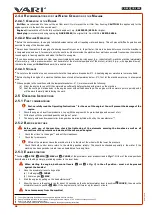
The gripping points for manual lifting are marked with the hand symbol -
Fig. 2
B
:
at the rear of the machine, tubular handlebar holder
at the front of the machine beam in the engine plate
2.4.2 M
ACHINE
TRANSPORT
When transporting the machine in a car or other road vehicle, always secure the machine against any unexpected
movement with certified lashing straps.
•
Always flip and lock the handlebars in the transport and parking position - see
Chap.2.4.3.1 Handlebar adjustment
on page
.
•
Always place the machine with its front end (= brushes) in or across the direction of travel of the vehicle.
•
The binding points are (straps are shown by thick lines in
Fig. 2
B
:):
at the rear of the machine, tubular handlebar holder
at the front of the machine support wheel
eye on the left on the engine plate
46
When the sweeping rollers are set to the middle position, when the machine's sweeping stroke is maximised as shown in the table.
47
For more information about the engine, including the spare parts numbers, go to
www.honda-engines-eu.com
48
Engine type designation may change. Please refer to the engine block for the current engine type specification designation.
49
Short term - up to one minute.
50
Measured per new standard
Society of Automotive Engineers (SAE) J 349
51
With regard to the ever increasing ratio of BIO-components in fuel, use fuel stabilizer.
26
re
vi
ze
1
2/
20
21


