Section 5
Page 16 of 24
18 Feb 2015
5.2
Fault / Service Indications – Requiring Operator Intervention.
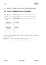
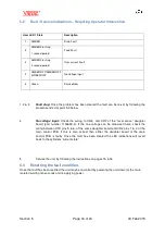
1, 2 & 3
Fault stop:
Once the problem has been cleared the fault can be re-set by following the
procedure listed at point 5.3 below.
4
No voltage input:
Check the wiring to CR6 and CR7 of the “level sense” daughter
board (part number 1150633-3). If the line voltage can be measured here, check the
wiring between CR1 pins 5 & 6, of the same daughter board and CR2 pins 1 & 3 of the
main control PCB. If this is also correct then either the daughter board or the main
control PCB is faulty. Once the fault has been cleared the LED indications will revert
back to the cylinders “current state”.
5
Service the unit, by following the instructions on pages 15 & 16.
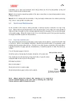
5.3
Resetting the fault condition.
Once the fault has been rectified the unit may be re-started by powering the unit down (at the main
isolator) waiting ten seconds and re-applying power.
User LED 1 State
Description
1
AMBER
Drain Fault
2
AMBER Flashing
1 second period
Feed Fault
3
AMBER Flashing
2 second period
Over current Fault
4
AMBER/OFF/AMBER/OFF
/GREEN/OFF
No Voltage input
5
Green
Service Now


