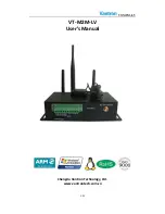
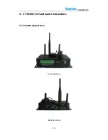
background image

VT-M2M-LV   


5

21


1.5


Limitation


of


Liability/Non

warranty


For


direct


or


indirect


damage


to


this


device


or


other


devices


of


Vantron


caused


by


failure


of


conforming


to


this


manual


or


the


safety


instructions


on


device


label,


Vantron


assumes


neither


warranty


nor


legal


liability


even


if


the


device


is


still


under


warranty.


The


VT

M2M

LV


should


be


installed,


debugged


and


maintained


by


professional


people.


The


outside


antennas


are


not


permitted


to


be


installed


or


to


be


changed


by


non

professional


people.


To


run


the


device


normally,


only


specify


antennas


are


approved


to


be


assembled


together


by


professional


people.


Unit


shall


be


used


with


indoor

use


antenna


only.


No


antenna


for


this


unit


can


be


installed


outdoor.


1.6


Safety


Instructions


Keep


and


comply


with


all


operation


instructions,


warnings,


and


information.


Pay


attention


to


warnings


on


this


device.


Read


the


following


precautions


so


as


to


decrease


the


danger


of


injury,


electric


shock,


fire,


or


any


damage


to


the


device.


1.7


Precautions


Pay


attention


to


the


product


labels/safety


instructions


printed


on


silk


screens.


Do


not


try


repairing


this


product


unless


declared


in


this


manual.


Keep


away


from


heat


source,


such


as


heater,


heat


dissipater,


or


engine


casing.


Do


not


insert


other


items


into


the


slot


(if


any)


of


this


device.


Keep


the


ventilation


slot


ventilated


for


cooling.


•System


fault


may


arise


if


other


items


are


inserted


into


this


device.


Installation:


ensure


correct


installation


according


to


instructions


from


the


manufacturer


with


recommended


installation


tools.


Ensure


ventilation


and


smoothness


according


to


relevant


ventilation


standard.


1.8


Safety


Instructions


for


Power


Cables


and


Accessories


Proper


power


source


only


Start


only


with


power


source


that


satisfies


voltage


label


and


the


voltage


necessary


according


to


this


manual.


Please


contact


technical


support


personnel


of


Vantron


for


any


uncertainty


about


the


requirements


of


necessary


power


source.


Use


tested


power


source


This


product


still


contains


a


button


lithium


battery


as


a


real

time


clock


after


its


external


power


source


is


removed


and


therefore


should


not


be


short

circuited


Содержание VT-M2M-LV

Страница 1: ...VT M2M LV 1 21 VT M2M LV User s Manual Chengdu Vantron Technology Ltd www vantrontech com cn ...

Страница 2: ...V3 0 Upgrade PCB to Revision 3 move GPS to on board change WiFi to on board module Sept 28 2014 4 V3 1 Add FCC and IC warning statement March 16 2015 5 V3 2 Add FCC and IC ID April 8 2015 6 V3 3 Add IC warning April 17 2015 7 V3 4 Add 3G module configuration information May 26 2015 8 V3 5 Add 4G module configuration information Dec 14 2017 ...

Страница 3: ...iew 7 2 1 Introduction 7 2 2 Product Series 8 3 M2M LV Hardware Instructions 9 3 1 Product Appearance 9 3 2 Specifications 10 3 3 Interface Instructions 11 3 4 Dimension 12 3 5 Interface Description 13 3 5 1 Power Interface 13 3 5 2 Ethernet Interface 14 3 5 3 D Sub 9 RS232 or RS485 Connector 15 3 5 4 RS232 422 485 CAN External IO Connector 16 3 5 5 LED 17 3 5 6 SIM Card 17 3 5 7 DEBUG 17 3 5 8 Re...

Страница 4: ...mation Vantron Technology Vantron E mail sales vantrontech com The trademarks and registered trademarks in this manual are properties of their respective owners No part of this manual may be copied reproduced translated or sold No changes or other purposes are permitted without the prior written consent of Vantron Vantron reserves the right of all publicly released copies of this manual 1 2 Notes ...

Страница 5: ...y damage to the device 1 7 Precautions Pay attention to the product labels safety instructions printed on silk screens Do not try repairing this product unless declared in this manual Keep away from heat source such as heater heat dissipater or engine casing Do not insert other items into the slot if any of this device Keep the ventilation slot ventilated for cooling System fault may arise if othe...

Страница 6: ...leaning the device Do not use spray detergent Clean with a damp cloth Do not try cleaning exposed electronic components unless with a dust collector Support for special fault Power off and contact technical support personnel of Vantron in case of the following faults The device is damaged The temperature is excessively high Fault is still not solved after the operation according to the manual ...

Страница 7: ...ed devices equipped with the state of the art technology and the best product services Vantron s M2M products are based on the most advanced ARM or Intel Atom processors and have low power consumption and high integration The products are designed for applications of M2M in industrials medicals financial retail vehicle and transportations etc ...

Страница 8: ...ND 3G module WLAN Accessories Install Mechanical tools 1pc Power Adapter Optional 1pc IO Terminal 12x3 81mm Optional 1pc Power Terminal 3x3 81mm Optional 1pc 3G Antenna Optional 1pc or 4G Antenna Optional 1 or 2 pc WiFi Antenna Optional 1pc GPS Antenna Optional 1pc Version I Extended Temperature Blank Commercial temperature Wireless Module Option 2G 2G 3G 3G 4G 4G W WLAN Z Zigbee P GPS NAND Memory...

Страница 9: ...VT M2M LV 9 21 3 VT M2M LV Hardware Instructions 3 1 Product Appearance Front Side View Back Side View ...

Страница 10: ...al or RF 2 4G Peripheral Interfaces Ethernet 1x10 100M BaseT RJ45 COM Port 1xDB9 RS232 485 1xRS232 485 422 1xCAN 2 0b up to 1Mbit s Alarm Buzzer Out SD card 1xSD card Slot Optional RTC Supported GPIO Reserved GPIO X4 Terminal Security Security Option al On board Registration Serial Number and SHA 1 Encrypt Decrypt Chip DS28E01 Power Input DC6 36V default 12V Locked Power Jack Consumption TBD Envir...

Страница 11: ...VT M2M LV 11 21 3 3 Interface Instructions Front Side View Back Side View Left Side View ...

Страница 12: ...VT M2M LV 12 21 3 4 Dimension ...

Страница 13: ...VT M2M LV 13 21 3 5 Interface Description 3 5 1 Power Interface Power connector outlook Pin Description 1 Shell ground 2 Power input range 6 36V 3 Ground PIN1 ...

Страница 14: ...rface Standard RJ45 interface supporting 10M 100M self adaptation this is a standard RJ45 Ethernet port Pin Description Remarks 1 TXP IO 2 TXN IO 3 RXP IO 4 CT P 5 CT 6 RXN IO 7 NC 8 MH_GND P 9 LEDG P 10 LINKLED 11 LEDY P 12 ACTIVITYLED ...

Страница 15: ...VT M2M LV 15 21 3 5 3 D Sub 9 RS232 or RS485 Connector Standard vertical DB 9 male connector Pin Description Remarks 1 NC or RS485_A 2 RXD2 or RS485_B I 3 TXD2 O 4 NC 5 DGND P 6 NC 7 NC 8 NC 9 NC ...

Страница 16: ... more than 128 nodes RS485 channel bit rate 115200 CAN The bit rate can be programmed to a maximum of 1Mbit s Pin Description Remarks 1 CANH 2 CANL 3 TX422 4 TX422 5 RX422 RS485_2_A STXD3 Jumper Set 6 RX422 RS485_2_B SRXD3 Jumper Set 7 DGND P 8 IO_GND P 9 GPIO_OUT1 IO 10 GPIO_OUT2 IO 11 GPIO_IN1 IO 12 GPIO_IN2 IO PIN1 ...

Страница 17: ... by themself 3 5 6 SIM Card Push the small button on the left of SIM Card Holder and install the SIM card to the holder Then push the holder into the Slot 3 5 7 DEBUG CONN BOX 1x3x2 0 TH JST VERT JST B3B PH K S LF SN User can show the debug message and use keyboardinput debug command Pin Description 1 DGND 2 SUART2_RXD 3 SUART2_TXD PIN1 ...

Страница 18: ...store the factory setting the long press time can be setting by user 3 5 9 Reset button Reset button Press this button shortly will reset this M2M device 3 5 10 SD MMC socket This is standard SD card socket user can save data on this storage You can remove this metal cover by use screw driver tool ...

Страница 19: ...tted to open the enclosure to adjust and replace the structure and components of the device Do not change components unless the power cord is removed In some cases the device may still have residual voltage even if the power cord is removed Therefore it is a must to remove and fully discharge the device before contact so as to avoid injury Unauthorized changes to this product or its components are...

Страница 20: ...r change components unless with permission and certification Please contact the technical support department of Vantron or local branches for help FCC ID 2AAGEVTM2M LV IC 1152A VTM2MLV contains FCC ID RI7HE910 IC 5131A HE910 FCC ID 2AAGEVTM2M LV IC 1152A VTM2MLV contains FCC ID RI7DE910 DUAL IC 5131A DE910DUAL FCC ID 2AAGEVTM2M LV IC 1152A VTM2MLV contains FCC ID RI7GE910Q3 IC 5131A GE910Q3 FCC ID...

Страница 21: ...ress No 5 GaoPeng Road Hi Tech Zone Chengdu SiChuan P R China 610045 Tel 86 28 8512 3930 3931 8515 7572 6320 Email sales vantrontech com cn US Office Vantron Technology Inc Address 1292 Kifer Road 807 Sunnyvale CA 94086 Tel 510 304 7666 Email sales vantrontech com ...

Отзывы: