


FPA-C34, FPA-W34
3
/
17
Table
of
Contents
1.
Foreword
................................................................................................................................
4
1.1
Copyright
Notice
........................................................................................................................4
1.2
Notes
..........................................................................................................................................4
1.3
Statement
...................................................................................................................................4
1.4
Disclaimer
...................................................................................................................................4
1.5
Limitation
of
Liability/Non
‐
warranty
..........................................................................................4
1.6
Safety
Instructions
......................................................................................................................5
1.7
Precautions
.................................................................................................................................5
1.8
Safety
Instructions
for
Power
Cables
and
Accessories
...............................................................5
2.
Overview
................................................................................................................................
7
2.1
Introduction
...............................................................................................................................7
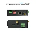
3.
M2M
Gateway
‐
FPA
‐
C34
,
FPA
‐
W34
Hardware
Instructions
......................................................
9
3.1
Product
Appearance
...................................................................................................................9
3.5
Interface
Description
...............................................................................................................
10
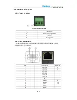
3.5.1
Power
Interface
........................................................................................................
10
3.5.2
Ethernet
Interface
....................................................................................................
10
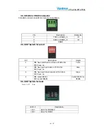
3.5.3
RS232
or
RS485
Connector
......................................................................................
11
3.5.3
DIP
Switch
for
select
................................................................................................
11
3.5.3
DIP
Switch
for
boot
..................................................................................................
11
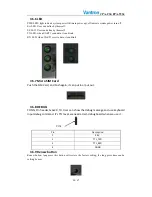
3.5.6
LED
...........................................................................................................................
12
3.5.7
Micro
SIM
Card
........................................................................................................
12
3.5.8
DEBUG
......................................................................................................................
12
3.5.9
Renew
button
..........................................................................................................
12
3.5.12
SD/MMC
socket
.....................................................................................................
13
4.
Tips
......................................................................................................................................
14