background image

www.fmiproducts.com

125502-01D

7

AIR FOR COMBUSTION AND VENTILATION

Continued

1.  Determine the volume of the space (length 

x width x height).


Length x Width x Height =__________cu. ft. 

(volume of space)


Example:

 Space size 20 ft. (length) x 16 ft. 

(width) x 8 ft. (ceiling height) = 2560 cu. ft. 

(volume of space)


If additional ventilation to adjoining room 

is supplied with grills or openings, add the 

volume of these rooms to the total volume 

of the space.

2.  Multiply the space volume by 20 to determine 

the maximum Btu/Hr the space can support.


 ________ (volume of space) x 20 = (Maxi-

mum Btu/Hr the space can support)


Example:

 2560 cu. ft. (volume of space) x 20 

= 51,200 (maximum Btu/Hr the space can 

support)

3.  Add the Btu/Hr of all fuel burning appliances 

in the space.


Vent-free fireplace 

 __________ Btu/Hr


Gas water heater* 

 __________ Btu/Hr


Gas furnace 

 __________ Btu/Hr


Vented gas heater   __________ Btu/Hr


Gas fireplace logs 

 __________ Btu/Hr


Other gas appliances* + ________ Btu/Hr

 Total 

= _________ Btu/Hr


* Do not include direct-vent gas appliances. 

Direct-vent draws combustion air from the 

outdoors and vents to the outdoors.


Example:


Gas water heater 

 _________ Btu/Hr


Vent-free fireplace 

+

 ________ Btu/Hr

 Total 

 _________ = Btu/

Hr

4.  Compare the maximum Btu/Hr the space can 

support with the actual amount of Btu/Hr used.


 _____ Btu/Hr (maximum the space can 

support) 


 ______Btu/Hr (actual amount of Btu/Hr used)


Example:

  51,200  Btu/Hr  (maximum  the 

space can support)


73,000 Btu/Hr (actual amount of 

Btu/Hr used)

The space in the above example is a confined 

space because the actual Btu/Hr used is more 

than the maximum Btu/Hr the space can sup-

port. You must provide additional fresh air. Your 

options are as follows:

A.  Rework worksheet, adding the space of an 

adjoining room. If the extra space provides 

an unconfined space, remove door to adjoin

-

ing  room  or  add  ventilation  grills  between 

rooms. See 

Ventilation Air From Inside 

Building

, page 8

.

B.  Vent room directly to the outdoors. See 

Ventilation Air From Outdoors, 

page 8.

C.  Install a lower Btu/Hr fireplace, if lower Btu/

Hr size makes room unconfined.

If the actual Btu/Hr used is less than the maxi-

mum Btu/Hr the space can support,


the space is 

an unconfined space. You will need no additional 

fresh air ventilation.

 WARNING: If the area in which 

the heater may be operated does 

not meet the required volume for 

indoor combustion air, combus

-

tion and ventilation air shall be 

provided by one of the methods 

described in the 

National Fuel 

Gas Code, ANSI Z223.1/NFPA 54, 

the

 International Fuel Gas Code,


or applicable local codes.

VENTILATION AIR

Ventilation Air From Inside Building

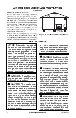
This fresh air would come from an adjoining 

unconfined  space.  When  ventilating  to  an 

adjoining unconfined space, you must provide 

two permanent openings: one within 12" of the 

ceiling and one within 12" of the floor on the 

wall connecting the two spaces (see options 

1 and 2, Figure 2). You can also remove door 

into adjoining room (see option 3, Figure 2). 

Follow  the 

National Fuel Gas Code, ANSI 

Z223.1/NFPA 54, Air for Combustion and 

Ventilation

  for  required  size  of  ventilation 

grills or ducts.

  40,000
  33,000
  73,000

Figure 2 - Ventilation Air from Inside 

Building

Or

Remove

Door into
Adjoining

Room,
Option

3

Ventilation Grills 

Into Adjoining Room,

Option 2

Ventilation

Grills Into

Adjoining 

Room,

Option 1

12"

12"

Содержание LVD18-CH

Страница 1: ...uilding Immediatelycallyourgassupplierfromaneighbor s phone Follow the gas supplier s instructions If you cannot reach your gas supplier call the fire department Installation and service must be performed by a quali fied installer service agency or the gas supplier INSTALLER Leave this manual with the appliance CONSUMER Retain this manual for future reference UNVENTED VENT FREE GAS LOG HEATER OWNE...

Страница 2: ...allation only in a solid fuel burn ing masonry or UL127 factory built fireplace or in a listed ventless firebox enclosure It is design cer tifiedfortheseinstallations in accordance with ANSI Z21 11 2 Exception Donot install this appliance in a factory built fireplace that includes instructions stat ing it has not been tested or should not be used with unvented gas logs WARNING This is an unvented ...

Страница 3: ...rnings Keep this manual for reference It is your guide to safe and proper operation of this heater WARNING Any change to this heater or its controls can be dangerous WARNING Do not use a blower insert heat exchanger insertorotheraccessorynotap proved for use with this heater SAFETY Continued WARNING Donotallowfans toblowdirectlyintothefireplace Avoidanydraftsthatalterburner flame patterns Ceiling ...

Страница 4: ... are no obstructions across openings of fireplace 8 To prevent the creation of soot follow the instructions in Cleaning and Maintenance page 22 9 Before using furniture polish wax carpet cleaner or similar products turn heater off If heated thevaporsfromtheseproductsmay create a white powder residue within burner box or on adjacent walls and furniture 10 This heater needs fresh outside air venti l...

Страница 5: ...R 30 upon sale of the unit Vent free gas products are prohibited for bedroom and bathroom installation in the Commonwealth of Massachusetts LOCAL CODES Install and use heater with care Follow all local codes In the absence of local codes use the latest edition of The National Fuel Gas Code ANSI Z223 1 NFPA 54 Available from American National Standards Institute Inc 1430 Broadway New York NY 10018 ...

Страница 6: ...ly tight construction you must provide additional fresh air Unusually tight construction is defined as construction where a walls and ceilings exposed to the out side atmosphere have a continuous water vapor retarder with a rating of one perm 6 x 10 11 kg per pa sec m2 or less with openings gasketed or sealed and b weather stripping has been added on openable windows and doors and c caulking or se...

Страница 7: ...cause the actual Btu Hr used is more than the maximum Btu Hr the space can sup port You must provide additional fresh air Your options are as follows A Rework worksheet adding the space of an adjoining room If the extra space provides an unconfined space remove door to adjoin ing room or add ventilation grills between rooms See Ventilation Air From Inside Building page 8 B Vent room directly to th...

Страница 8: ...ng system Do not install this heater as your pri mary heat source If you have a centralheatingsystem youmay run system s circulating blower whileusingheater Thiswillhelp circulatetheheatthroughoutthe house In the event of a power outage you can use this heater as your primary heat source WARNING A qualified ser vice person must install heater Follow all local codes CAUTION This heater cre ates war...

Страница 9: ...rovide greater clearances from floor ceiling and adjoining wall Carefully follow these instructions This will ensure safe installation into a masonry UL127 listed manufactured fireplace or listed vent free firebox Minimum Clearances For Side Combustible Material Side Wall and Ceiling A Clearances from the side of the fireplace cabinet to any combustible material and wall should follow diagram in F...

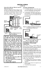
Страница 10: ...erial must extend at least 8 inches up for all models If noncombustible material is less than 12 you must install the fireplace hood accessory 24 Models Only Even if noncombustible material is more than 12 you may need the hood accessory to deflect heat away from your mantel shelf See Figure 5 and Figures 6 and 7 page 11 for minimum clearances IMPORTANT If you cannot meet these mini mum clearances...

Страница 11: ...ing hood NOTICE Surface temperatures of adjacent walls and mantels become hot during operation Walls and mantels above the firebox may become hot to the touch If installed properly these temperatures meet the requirement of the national product standard Follow all minimum clearances shown in this manual NOTICE Ifyourinstallationdoes not meet the minimum clear ances shown you must do one of the fol...

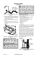
Страница 12: ... to heater control panel This will in sure adequate air flow and guard against sooting and controls being damaged Raise fireplace floor with noncombustible mate rial Makesurematerialissecure CAUTION Do not pick up heater base assembly by burn ers This could damage heater Only handle base assembly by grates IMPORTANT Make sure the heater burners are level If heater is not level heater will not work...

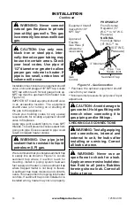
Страница 13: ...or not supplied Install the external regulator between the heater and propane LP supply Installation Items Needed Before installing heater make sure you have the items listed below external regulator supplied by installer piping check local codes sealant resistant to propane LP gas equipment shutoff valve test gauge connection sediment trap tee joint pipe wrench A equipment shutoff valve with 1 8 ...

Страница 14: ...ment shutoff valve is for turning on or shutting off the gas to the appliance Check your building codes for any special requirements for locating equipment shutoff valve to fireplaces Apply pipe joint sealant lightly to male NPT threads This will prevent excess sealant from going into pipe Excess sealant in pipe could result in clogged heater valves WARNING Use pipe joint sealant that is resistant...

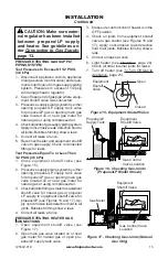
Страница 15: ... and equipment shutoff valve to gas supply Check reconnected fittings for leaks Test Pressures Equal To or Less Than 1 2 PSIG 3 5 kPa 1 Close equipment shutoff valve see Figure 15 2 Pressurize supply piping system by either opening propane LP supply tank valve for propane LP gas or opening main gas valve located on or near gas meter for natural gas or using compressed air 3 Checkalljointsfromgasme...

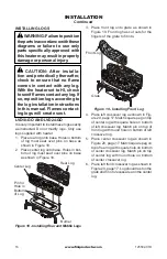
Страница 16: ...n and periodically thereafter check to ensure that no flame comes in contact with any log With the heater set to HI check toseeifflamescontactanylog If so reposition logs according to the log installation instructions in this manual Flames contact ing logs will create soot 4 Place left crossover log as shown in Fig ure 20 page 17 Match square peg on top of center log with square hole on bottom of ...

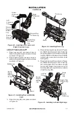
Страница 17: ...Middle Logs Burner Middle Log Rear Log Pin for Hole in Bottom of Log Figure 22 Installing Front Log Figure 23 Installing Left and Right Logs Front Log Grate Left Top Log Square Peg on Rear Log Right Top Log Round Peg on Front Log 3 Place front log 3 onto grate as shown in Figure 22 4 Place left top log 4 as shown in Figure 23 Match square peg on top of rear log 1 with square hole on bottom of left...

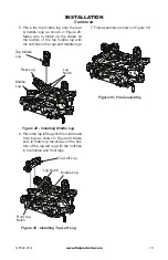
Страница 18: ...27 Installing Top Right Log Figure 25 Installing Middle Log 2 Place the middle log on base Holes in bottom of log must seat over pins on base as shown in Figure 25 3 Place the front log onto grate as shown in Figure 26 4 Place the top right log onto the rear middle and front logs as shown in Figure 27 The rear middle and front logs has notches for the top right log to set into You may have to move...

Страница 19: ...ure to match up the shape on the bottom of the top middle log with the notches in the rear and middle logs 6 Place the top left log onto the middle and front logs as shown in Figure 29 Make sure to match up the shape on the bot tom of the top left log with the notches in the middle and front logs 7 Final assembly is shown in Figure 30 Top Middle Log Log Notch Log Notch Front Log Notch Middle Log R...

Страница 20: ...ppliance and to replace any part of the control system and any gas control which has been under water LIGHTING INSTRUCTIONS WARNING If fireplace has glass doors never operate this heater with glass doors closed If you op erateheaterwithdoorsclosed heat buildup inside fireplace willcauseglasstoburst Make suretherearenoobstructions across opening of fireplace You must operate this heater withafirepl...

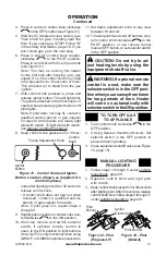
Страница 21: ... a qualified service person or gas supplier for repairs Note If pilot goes out repeat steps 4 through 8 9 Slightly push in and turn control knob coun terclockwise to the ON position 10 Wait one minute and switch selector switch if optional remote control is used to the ON position to light burners Note AUTO is only functional when using GWMT1 or GWMS2 optional accessories Figure 32 Pilot Propane L...

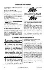
Страница 22: ... needed Blocked air holes will create soot INSPECTING BURNERS Figure 34 Correct Pilot Flame Pattern Your pilot may vary from pilot shown Pilot Burner Thermocouple Pilot Burner Thermocouple Figure 35 Incorrect Pilot Flame Pattern Your pilot may vary from pilots shown MAIN BURNER Periodically inspect all burner flame holes with the heater running All slotted burner flame holes should be open with ye...

Страница 23: ...st have now been pushed into the burner repeat steps 3 and 4 Clean the pilot assembly also A yellow tip on the pilot flame indicates dust and dirt in the pilot assembly There is a small pilot air inlet hole about two inches from where the pilot flame comes out of the pilot assembly see Figure 37 With the unit off lightly blow air through the air inlet hole You may blow through a drinking straw if ...

Страница 24: ... in stalled 5 Depleted gas supply pro pane LP only 6 ODS pilot is clogged 7 Gas regulator setting is not correct REMEDY 1 Reconnect ignitor cable 2 Free ignitor cable if pinched by any metal or tubing Keep ignitor cable dry 3 Tighten nut holding piezo ignitor to base panel of log set Nut is located behind base panel 4 Replace ignitor cable 5 Replace piezo ignitor 6 Replace pilot assembly 7 Replace...

Страница 25: ...r ODS pilot lights keep control knob pressed in 30 seconds 3 Wait one minute for safety interlock system to reset Repeat ignition operation 4 Fully open equipment shut off valve 5 A Contact local natural or propane LP gas company B Clean ODS pilot see Cleaning and Maintenance page 22 or replace ODS pilot assembly 6 Hand tighten until snug then tighten 1 4 turn more 7 Replace pilot assembly 8 Repla...

Страница 26: ...checked by local natural or propane LP gas company 3 Observe minimum installa tion clearances see pages 9 through 11 4 Clean burners see Cleaning and Maintenance page 22 or replace burner orifice 1 Turn heater off when us ing furniture polish wax carpet cleaners or similar products 1 Refer to Air for Combustion and Ventilation require ments page 6 1 Properly locate logs see Installing Logs page 16...

Страница 27: ...leaning and Maintenance page 22 1 Locate and correct all leaks see Checking Gas Con nections page 14 2 Replace control valve 1 Take apart gas tubing and remove foreign matter 2 Locate and correct all leaks see Checking Gas Con nections page 14 OBSERVED PROBLEM Heater produces unwanted odors Heater shuts off in use ODS operates Gas odor even when control knob is in OFF position Gas odor during comb...

Страница 28: ...www fmiproducts com 125502 01D 28 PARTS BURNER SYSTEMS VD1824NR AND VD1824PR 14 3a 16 18 19 1 3b 1 2 1 12 13 5 11 6 2 17 4 10 7 8 9 15 ...

Страница 29: ... 1 099387 12 Pilot Tube 1 8 099918 02 Pilot Regulator 1 9 100609 01 Tube 1 10 103778 01 Pilot ODS LP 1 103779 01 Pilot ODS NG 1 11 103781 05 Gas Valve NG 1 103781 06 Gas Valve LP 1 12 103784 01 Knob Extension HI LO 1 13 103784 02 Knob Extension ON OFF 1 14 126356 01 Grate 1 15 120786 01 Burner NG 1 120786 02 Burner LP 1 16 Log Base 1 17 124934 01 Heat Shield 1 18 117004 01 Pilot Shield 4 19 124699...

Страница 30: ...1 2 124673 02 Center Log 1 124674 02 Center Log 1 3 124673 03 Rear Log 1 124674 03 Rear Log 1 4 124673 04 Left Crossover Log 1 124674 04 Left Crossover Log 1 5 124673 05 Center Crossover Log 1 124674 05 Center Crossover Log 1 6 124673 06 Right Front Crossover Log 1 124674 06 Right Front Crossover Log 1 L V D 1 8 G O L V D 2 4 G O 4 5 1 3 6 2 ...

Страница 31: ...TION QTY 1 123190 01 Rear Log 1 123190 06 Rear Log 1 2 123190 02 Middle Log 1 123190 07 Center Log 1 3 123190 03 Front Log 1 123190 08 Front Log 1 4 123190 04 Top Right Log 1 123190 09 Top Right Log 1 5 123190 10 Top Left Log 1 123190 05 Top Left Log 1 L V D 1 8 P P L V D 2 4 P P 5 3 1 4 2 ...

Страница 32: ...KEY NO PART NUMBERS DESCRIPTION QTY LVD18 CH LVD24 CH 1 125959 04 125959 05 Rear Log 1 1 2 125959 03 125959 03 Middle Log 2 1 3 125959 01 125959 02 Front Log 3 1 4 125959 08 125959 08 Top Right Log 4 1 5 125959 07 125959 07 Top Middle Log 5 1 6 125959 06 125959 06 Top Left Log 6 1 ...

Страница 33: ... 0 w c Inlet Supply Pressure inches of water Maximum 14 w c Minimum 11 w c VD1824NR Rating 25 000 36 000 Btu hr Gas Type Natural Ignition Piezo Manifold Pressure 3 5 w c Inlet Supply Pressure inches of water Maximum 10 5 w c Minimum 5 w c SERVICE HINTS When Gas Pressure Is Too Low pilot will not stay lit burners will have delayed ignition heater will not produce specified heat for propane LP units...

Страница 34: ...an be selected on the wall thermostat and the log heater will auto matically cycle from pilot to the heat setting selected WALL MOUNT ON OFF SWITCH GWMS2 For all Remote Ready Models Allows the gas log heater to be turned on and off with a wall switch DAMPER CLAMP GA6080 For Remote Ready and Variable Manually Controlled Models Permanently opens chimney flue damper for vented operation LAVA ROCK GA6...

Страница 35: ..._______________________________ ______________________________________________________ ______________________________________________________ ______________________________________________________ ______________________________________________________ ______________________________________________________ ______________________________________________________ ______________________________________...

Страница 36: ...is product and or FMI PRODUCTS LLC who will provide original factory replacement parts Failure to use original factory replacement parts voids this warranty Travel handling transportation diagnostic material labor and incidental costs associated with warranty repairs unless expressly covered by this warranty are not reimbursable under this warranty and are the responsibility of the owner Excluded ...

Отзывы: