I N S T A L L A T I O N
©Vantage, 7/23/2015 / IS-0541-A
Equinox 40 LCD Keypad – MODEL: EQ40TB-TI-II
page 2 of 6
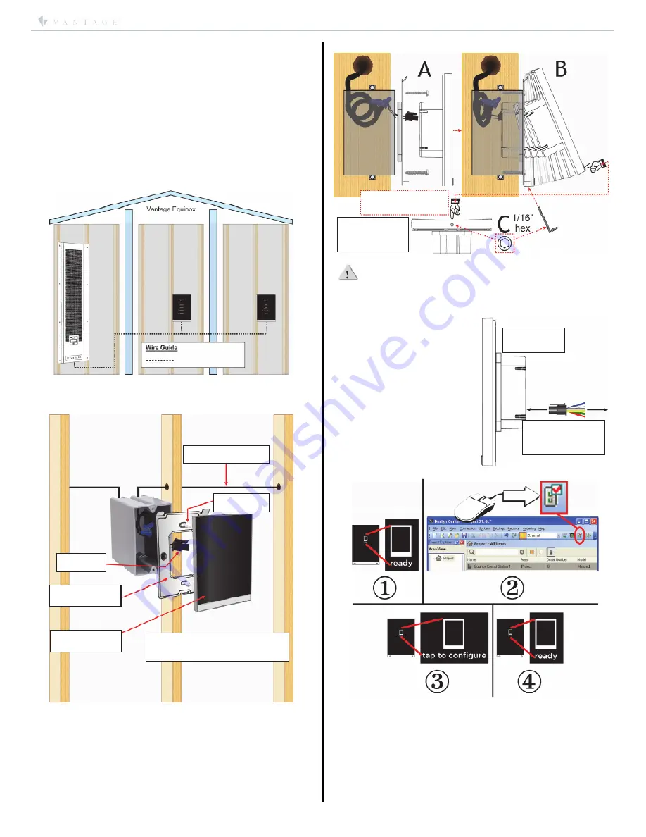
Station Bus*
Enclosure
Equinox
Keypad
Equinox
Keypad
Six Wire Pigtail
for sensors, dry
contacts, etc.
Equinox 40
keypad
pigtail
mounting
plate
Equinox 40
LCD keypad
station bus
Screws*
*Use flat-head screws provided
US – 6-32 x 0.75
″
or
Metric – M3.5 x 20mm
Set 1/16” hex
screw in
station bottom
Press here on front,
bottom, center
System Requirements
Equinox 40 is compatible with InFusion Design Center version
3.1 software or higher. For new projects it is recommended
that firmware and software be kept to the most current
release.
Installation
Installation of Vantage products should be performed or
supervised by a
Certified Vantage Installer.
The Vantage
Equinox 40 keypad installs into US/European style, single
gang, wall boxes or low-voltage brackets. Connect to station
bus. See
Troubleshooting, Expectations and Tips
page 5. Do
not touch the screen when first powered or reset until it boots.
I.
Installation Overview
* See Vantage
Station Bus Specification
– table, page 1.
Vantage Station Bus may be ordered separately.
Station Install Steps
1.
Run station bus to boxes.
2.
Install mounting plate
with screws provided
(see
A
in
*
Side
View Illustration
)
. Do not bend mounting plate
3.
Connect pigtail to station.
4.
Install station by rotating
(see
B
in
*
Side View Illustration
)
and
connecting the top first. Then press station in and hold on
bottom center while securing the hex screw with provided
allen wrench
(see
C
in
*
Side View Illustration
)
.
*Side View Illustration:
CAUTION:
Do not over tighten the 1/16” hex screw in station
bottom. If screw will not go in, the mounting plate may need
slightly loosened and/or have a thin spacer inserted between
the wall and mounting plate. The wall must be repaired if
there is still a problem.
Auxiliary Connections
Auxiliary connections to the
station are wired to a six wire
pigtail, including motion
detectors, door contacts, light
sensors, etc. Each aux.
connection supplies a 15mA @
12V DC power source,
eliminating the need for an
external power supply. Aux.
powered devices using the
Black wire should not be earth
grounded unless isolated.
II.
Configuration
1.
Connect station bus and confirm it says
ready
.
2.
Highlight station in Design Center; click
Configure Stations
.
3.
Station displays
tap to configure
– tap station.
4.
When configured station goes back to
ready
until
programmed.
-OR-
5.
The station may also be configured by typing the serial
number in the project file, using this method the station will
automatically be configured when the system is
programmed.


