


REV 2
ATRT-03, ATRT-03A, AND ATRT-03B USER’S MANUAL
32
i.
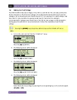
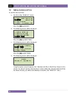
The following screen will be displayed:
Type the transformer’s KVA rating using the alpha-numeric keypad and then press the
[
ENTER
] key.
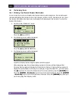
j.
The following screen will be displayed:
Type the operator’s name using the alpha-numeric keypad and then press the
[ENTER]
key. All header information will be saved, and you will be returned to the “START-UP”
menu.
OPERATOR:
_
UP/DOWN TO POSITION
“ENTER” TO ACCEPT
KVA RATING:
_
UP/DOWN TO POSITION
“ENTER” TO ACCEPT
Содержание ATRT-03
Страница 14: ...ATRT 03 ATRT 03A AND ATRT 03B USER S MANUAL REV 2 9 Figure 2 ATRT 03A Controls and Indicators...
Страница 16: ...ATRT 03 ATRT 03A AND ATRT 03B USER S MANUAL REV 2 11 Figure 3 ATRT 03B Controls and Indicators...
Страница 34: ...ATRT 03 ATRT 03A AND ATRT 03B USER S MANUAL REV 2 29 Press any key to return to the START UP menu...
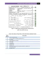
Страница 57: ...REV 2 ATRT 03 ATRT 03A AND ATRT 03B USER S MANUAL 52 Figure 20 Special Dy11 Transformer Test Printout...
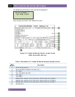
Страница 71: ...REV 2 ATRT 03 ATRT 03A AND ATRT 03B USER S MANUAL 66 Figure 21 Typical Test Record Directory Printout...
Страница 79: ...REV 2 ATRT 03 ATRT 03A AND ATRT 03B USER S MANUAL 74 Figure 22 Test Plan Test Results Printout...
Страница 85: ...REV 2 ATRT 03 ATRT 03A AND ATRT 03B USER S MANUAL 80 Figure 23 Sample Test Plan Printout...
Страница 90: ...ATRT 03 ATRT 03A AND ATRT 03B USER S MANUAL REV 2 85 APPENDIX B Common ANSI Transformer Descriptions...
Страница 91: ...REV 2 ATRT 03 ATRT 03A AND ATRT 03B USER S MANUAL 86...
Страница 92: ...ATRT 03 ATRT 03A AND ATRT 03B USER S MANUAL REV 2 87...
Страница 93: ...REV 2 ATRT 03 ATRT 03A AND ATRT 03B USER S MANUAL 88...
Страница 94: ...ATRT 03 ATRT 03A AND ATRT 03B USER S MANUAL REV 2 89...
Страница 95: ...REV 2 ATRT 03 ATRT 03A AND ATRT 03B USER S MANUAL 90...
Страница 96: ...ATRT 03 ATRT 03A AND ATRT 03B USER S MANUAL REV 2 91...
Страница 97: ...REV 2 ATRT 03 ATRT 03A AND ATRT 03B USER S MANUAL 92...
Страница 98: ...ATRT 03 ATRT 03A AND ATRT 03B USER S MANUAL REV 2 93 APPENDIX C CEI IEC 60076 1 Transformer Descriptions...
Страница 99: ...REV 2 ATRT 03 ATRT 03A AND ATRT 03B USER S MANUAL 94...
Страница 100: ...ATRT 03 ATRT 03A AND ATRT 03B USER S MANUAL REV 2 95...
Страница 101: ...REV 2 ATRT 03 ATRT 03A AND ATRT 03B USER S MANUAL 96...
Страница 102: ...ATRT 03 ATRT 03A AND ATRT 03B USER S MANUAL REV 2 97...
Страница 103: ...REV 2 ATRT 03 ATRT 03A AND ATRT 03B USER S MANUAL 98...
Страница 104: ...ATRT 03 ATRT 03A AND ATRT 03B USER S MANUAL REV 2 99...
Страница 105: ...REV 2 ATRT 03 ATRT 03A AND ATRT 03B USER S MANUAL 100 APPENDIX D Australian Std 2374 Transformer Descriptions...
Страница 106: ...ATRT 03 ATRT 03A AND ATRT 03B USER S MANUAL REV 2 101...
Страница 107: ...REV 2 ATRT 03 ATRT 03A AND ATRT 03B USER S MANUAL 102...
Страница 108: ...ATRT 03 ATRT 03A AND ATRT 03B USER S MANUAL REV 2 103...
Страница 109: ...REV 2 ATRT 03 ATRT 03A AND ATRT 03B USER S MANUAL 104...
Страница 110: ...ATRT 03 ATRT 03A AND ATRT 03B USER S MANUAL REV 2 105...
Страница 111: ...REV 2 ATRT 03 ATRT 03A AND ATRT 03B USER S MANUAL 106...


