


V&P Scientific, Inc.
2
Technical Note 083B
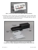
Figure 2. Parts of the VP 767-5A Motor Control Unit shown unassembled. Compatible with
any of the VP 758-5 series Direct Drive Bubble Paddle Reservoirs listed on previous page.
OPERATION
1)
To attach the VP 758-5 series Bubble Paddle Reservoir to the VP 767-5A motor, turn the Sealed
Bearing Coupler so that its spokes align with the slots in the motor coupler on the VP 767-5A
Motor Base. To slip the Sealed Bearing Coupler into the slots on the motor coupler, it helps to lift
slightly up on the end of the reservoir opposite of the Sealed Bearing while also gently pushing
toward the motor. Once the coupler is engaged press down on the lifted end of the reservoir and
it will “snap” into position
.
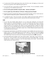
2)
If using with an automated liquid handler, place the VP 767-5A motor assembly on the deck using
the robot-specific locating features. Position the pipet tips to be aligned with the notches in the
bubble paddles and the depressions in the VP 758 series Bubble Paddle Reservoir (see Figure 3).
Motor
Base
Power
Cable
Control Unit
VP 758-5PP
Reservoir
Control
Cable
Power
Supply
Cable
Speed
Control
Dial
On/Off
Switch
Bubble
Paddle
Sealed
Bearing
Power
Supply


