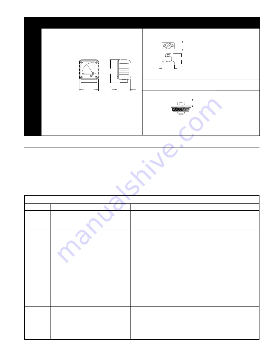
Vanair F200-15-1/4 Скачать руководство пользователя страница 7


PAGE 7

2-1/8"

2-1/8"

3-3/8"

2-1/4"

2-5/8"

1-1/2"

1/2"

1"

1-11/16"

1-7/8"

DIFFERENTIAL

 PRESSURE

INDICA

TOR KITS

PD-5 (P/N: 84-10001)

PD-6 (P/N: 84-10125)

KIT INCLUDES (1) PD-6, (2) SCREWS, (4) O-RINGS & 

INSTRUCTION SHEET.

FITS ALL MODELS EXCEPT F200-15-1/4 THRU 25-1/2.

FITS ALL MODELS EXCEPT F200-15-1/4 THRU 25-1/2.

ACCESSORIES CONT'D

MAINTENANCE

Drain coalescing filters every shift.

Check differential pressures weekly on coalescing and 

particulate filters (AA/RAA, A/RA, B/RB, and C/RC grades). 

When the indicator is red on differential pressure indicator, 

install clean elements. On adsorbing filters (grade RD), install 

clean elements when hydrocarbon vapors are first detected 

downstream or every six months, whichever comes first.

For correct replacement element model numbers, see label 

on filter housing, the bottom endcap of the element, or page 

5 of this instruction manual.

When changing out element, inspect housing o-ring for nicks 

and/or cracks. If nicks and/or cracks are present, replace    

o-ring.

PD-6A-C (P/N: 84-10126)

PD-6A-P (P/N: 84-10127)

FITS MODELS F200-15-1/4 THRU 25-1/2 ONLY.

PD-6A-C

FOR COALESCING 

FILTERS

PD-6A-P

FOR PARTICULATE 

FILTERS

KIT INCLUDES (1) PD-5, (2) SCREWS, (4) O-RINGS & 

INSTRUCTION SHEET.

*DIMENSIONS EXTENDING ABOVE FILTER HOUSING.

KIT INCLUDES (1) PD-6A, (2) O-RINGS & INSTRUCTION SHEET.

*DIMENSIONS EXTENDING ABOVE FILTER HOUSING.

*

*

*

   TROUBLE SHOOTING

CONDITION

POTENTIAL CAUSE

RECOMMENDATION

Initial pressure 

drop too high

Filter undersized for flow rate.

Install larger filter.

Filter grade too fine.

Install coarser grade element.

Filter inlet smaller than pipe size.

Install larger filter.

Oil carryover

Oil present in system before installing filter.

Clean piping.

Excessive inlet oil >50ppm.

Check compressor and/or gas/oil separator if compressor is rotary vane or screw type. 

Check lube rate if reciprocating compressor. Install coarse coalescer for prefiltration.

Filter installed backwards.

Check flow direction (See page 1).

Filter bowl not being drained.

Drain more frequently.

High differential pressure.

Check differential pressure indicator, replace element if necessary.

Defective seal.

Check o-ring in element.

Incorrect element grade.

Use finer grade.

By-pass valve leaking or open.

Close valve. Check seals on valve

Unfiltered gas entering from source down stream of 

filter.

Relocate filter or install additional filter.

High operating temperatures.

Install, clean, replace or relocate aftercooler, or relocate filter.

Cooling by refrigerated dryer.

Install grade C filter downstream of dryer.

Short element 

life

Excessive contamination.

Install coarse particulate filter immediately upstream of existing filter.

High compression temperatures causing varnish/

carbon formation.

Use compression lubricant with good temperature stability. Lower lube rates where pos-

sible. Use coarser grade filter element.

Oil/water emulsion overloading element.

Inspect moisture separator. Remove water with better separation.

High viscosity oil or freeze-up due to low ambient 

temperature.

Raise ambient temperatures. Heat trace inlet piping and housing.

Содержание F200-15-1/4

Страница 1: ...ll units include push on elements with durable polyester drain layer except RD grade Accessories include differential pressure indicators wall mounting kits connector kits and automatic drain valves OPERATING CONDITIONS MAXIMUM WORKING PRESSURE All Models OPERATING TEMPERATURE Minimum Maximum MAXIMUM RECOMMENDED INLET TEMPERATURE AA A RAA RA RB and RC Series B Series C Series RD Series 250 PSIG 35...

Страница 2: ... 5 16 2 1 16 29 3 8 6 9 9 2 3 F200 600 3 600 3 7 7 8 2 3 4 24 1 2 8 19 8 2 7 F200 800 3 800 3 7 7 8 2 3 4 30 1 16 8 21 9 3 6 F200 1000 3 1000 3 7 7 8 2 3 4 34 3 4 12 28 1 4 3 F200 1250 3 1250 3 7 7 8 2 3 4 34 3 4 12 28 1 4 3 F200 1600 3 1600 3 9 2 5 8 42 13 3 4 33 7 4 6 FLOW CAPACITIES AT VARIOUS OPERATING PRESSURES SCFM FILTER MODEL 25 PSIG 50 PSIG 75 PSIG 100 PSIG 125 PSIG 150 PSIG 175 PSIG 200 ...

Страница 3: ...lves Remove filter head from the bowl by turning bowl counter clockwise Pull element from locator Set bowl and element aside for use later Install inlet and outlet shutoff valves to facilitate replacement of element Bypass piping is recommended See Figure 1A and 1B MAKE SURE VALVES ARE CLOSED BEFORE PROCEEDING Connect filter head into piping Avoid reducers or bushings to matchinletsize Theresultin...

Страница 4: ...4 THRU 25 1 2 A 2 475 01000 4B BODY O RING FOR F200 55 1 2 B 1 475 00146 4C BODY O RING FOR F200 85 3 4 THRU 500 2 B 1 475 00242 4D BODY O RING FOR F200 600 3 THRU 1250 3 C 1 475 00362 4E BODY O RING FOR F200 1600 3 C 1 475 00367 5A 1 4 NPT FILTER HEAD FOR F200 15 1 4 A 1 201 00100 5B 3 8 NPT FILTER HEAD FOR F200 25 3 8 A 1 201 00110 5C 1 2 NPT FILTER HEAD FOR F200 25 1 2 A 1 201 00120 5D 1 2 NPT ...

Страница 5: ...0 85 C RC 26 2083 E200 800 C RC 26 10442 E200 85 RD 26 2153 E200 800 RD 26 10444 F200 100 1 E200 100 AA RAA 26 10035 F200 1000 3 E200 1000 AA RAA 26 10040 E200 100 A RA 26 2062 E200 1000 A RA 26 2067 E200 100 B RB 26 2073 E200 1000 B RB 26 2078 E200 100 C RC 26 2084 E200 1000 C RC 26 2089 E200 100 RD 26 2154 E200 1000 RD 26 2159 F200 150 1 E200 150 AA RAA 26 10036 F200 1250 3 E200 1250 AA RAA 26 7...

Страница 6: ...4 3 4 2 3 4 1 2 3 4 5 16 MB 3 2 7 1 8 4 15 16 1 3 16 3 15 16 3 8 INSTALLED MOUNTING BRACKET KIT DIMENSIONS TYPE USED ON PART NO A B C D E MB 1 55 84 0720 4 1 2 1 1 4 1 3 4 3 5 16 5 1 4 MB 1 2 15 THRU 25 84 10130 3 3 4 1 1 4 1 3 4 3 4 7 16 MB 2 85 THRU 265 84 0721 5 15 16 1 9 16 2 9 16 4 7 8 6 11 16 MB 2 2 350 THRU 500 84 10131 6 1 2 2 2 3 4 5 1 4 7 5 16 MB 3 2 600 THRU 1250 84 10132 9 5 16 3 3 4 3...

Страница 7: ...gh Filter undersized for flow rate Install larger filter Filter grade too fine Install coarser grade element Filter inlet smaller than pipe size Install larger filter Oil carryover Oil present in system before installing filter Clean piping Excessive inlet oil 50ppm Check compressor and or gas oil separator if compressor is rotary vane or screw type Check lube rate if reciprocating compressor Inst...

Страница 8: ...ERs DANGER WARNING READ THE OPERATOR S MANUAL BEFORE STARTING OR SERVICING THIS UNIT FAILURE TO ADHERE TO INSTRUCTIONS CAN RESULT IN SEVERE PERSONAL INJURY OR DEATH REPLACEMENT MANUALS CAN BE DOWNLOADED AT www vanairsystems com SAFETY PRECAUTIONS Safety is everybody s business and is based on your use of good common sense All situations or circumstances cannot always be predicted and covered by es...

Отзывы: