35in Series
Electric Profiles
Almost-Ready-to-Fly
Instruction Manual
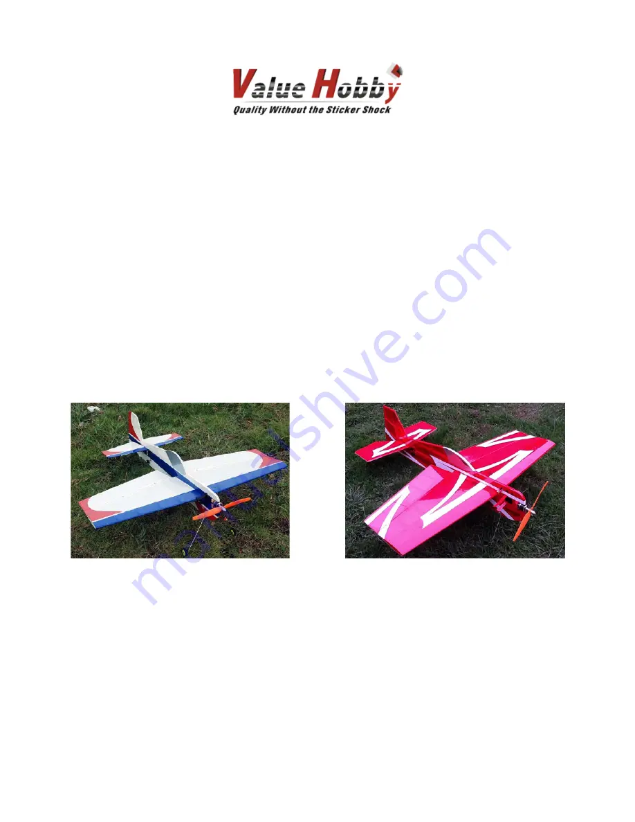
Cap 35
Sabre 35
Specifications
Wingspan: 35in (890mm)
Length: 37 in (940mm)
Wing Area: Approx. 350 sq in (22.6 sq dm)
Flying Weight: Approx. 20oz
Страница 1: ...5in Series Electric Profiles Almost Ready to Fly Instruction Manual Cap 35 Sabre 35 Specifications Wingspan 35in 890mm Length 37 in 940mm Wing Area Approx 350 sq in 22 6 sq dm Flying Weight Approx 20o...
Страница 2: ......
Страница 3: ...d nor materials used for the final user assembled product By the act of using the final product the user accepts all resulting liability Value Hobby as a R C product vendor provides a top quality airp...
Страница 4: ...he air This is a natural property of balsa wood As your airplane adjusts to the weather in your part of the world wrinkles may appear and disappear Wrinkles may be removed with the gentle application...
Страница 5: ...ess ESC 1 HWG SC 0238 Battery GForce 30C 1300mAh 3S 11 1V LiPO 1 RFI LP 0293 Prop EMP Neodym 10 X 5 Electric Scimitar Prop 1 XYH MP 0436 Servos Towerpro MG90S Metal Gear Micro Servo 4 TWP SV 0359 Y Ha...
Страница 6: ...ASSEMBLY Step 1 Using xacto knife and covering iron trim the covering over the wing opening tail stab opening and motor mount on the fuselage...
Страница 7: ...Step 2 From the parts bag find the plywood motor mount parts as shown below Assemble as shown below and secure with CA glue The assembly is slightly off center for the motor offset...
Страница 8: ...g gear foam wheels heat shrink tubing and zip ties Secure the wire landing gear using the zip ties Secure the foam wheels on the landing gear using heat shrink tubing Apply a few drops of CA on the he...
Страница 9: ...ep 4 Slot the wing inside the wing opening on the fuselage Make sure the wing is in line up properly with the fuselage Find the plywood control horns and glue them into the pre cut slots on the ailero...
Страница 10: ...joiner wire Follow the steps below test fit the two elevator halves secure the joiner wire onto the fin and install the fin onto the fuselage and secure the elevator to the fin Make sure you have the...
Страница 11: ...fuselage Step 7 Secure the landing skid to the fuselage with the ziptie Step 8 Make sure all the control surfaces are lined up properly A A B B C C D D After everything is properly positioned apply a...
Страница 12: ......
Страница 13: ...Step 9 Cut the covering over the servo openings and install the servos and connect the control surfaces For motor and power setup please refer to the recommended setup...
Страница 14: ...Step 10 Secure the motor speed controller and battery You can arrange the parts to your own preference but make sure the wires does not interfere with the motor or the servos...
Страница 15: ...Step 11 Set the CG location at the red dot position as shown below Control surfaces Elevator 35 45 degrees Aileron 30 40 degrees Rudder 35 45 degrees...