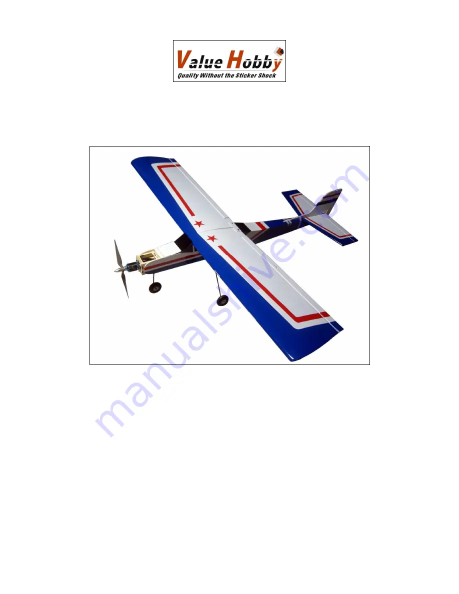
Aviator Trainer25 ARF
Instruction Manual
Specifications
Wingspan: 54.3in (1380mm)
Length: 45.2in (1150mm)
Wing Area: 438sq in (34sq dm)
Flying Weight: 3.8lbs (1700g)
Страница 1: ...Aviator Trainer25 ARF Instruction Manual Specifications Wingspan 54 3in 1380mm Length 45 2in 1150mm Wing Area 438sq in 34sq dm Flying Weight 3 8lbs 1700g...
Страница 2: ...er Value Hobby reserves the right to modify this warranty without notice Value Hobby has no control over the final stages of assembly or the material used for the final assembly No liability shall be...
Страница 3: ...or the first time you take the plane out to the flying field These wrinkles are the result of wood shrinkage and or expansion Balsa wood changes size and shape slightly as it is exposed to varying hum...
Страница 4: ...bbywing Flyfun 60A ESC HWG SC 0241 Battery GForce Elite Series 30C 2200mAh 3S 11 1V FLM LP 1802 Prop 12 x 6E EMX MP 1769 High Power Setup Product SKU Motor Gforce G25 35 48 850KV SAT MT 1882 ESC Hobby...
Страница 5: ...www valuehobby com aviator trainer 25 arf html 5 Main Parts Accessories...
Страница 6: ...ing Bolt Plate x 1 Round Head Screw M3 30mm 1 2inch x 2 M3 Washer x 2 M2 x10mm 0 4inch Self tapping Screws x 2 Pack5 Main Landing Gear Strut x 2 Nose Landing Gear x 1 Pushrod for Nose Wheel 1 5x380mm...
Страница 7: ...a gap between the aileron and the wing Also check the aileron can move freely without rubbing at the wing foot Step4 Saturate each hinges with thin CA make sure to glue both the top and bottom Once CA...
Страница 8: ...the wing out of the hole as shown The distance between the hole and the opening for servo is about 260mm 10 2inch you need to use a servo extension if your servo lead is not enough long Step4 Use a d...
Страница 9: ...one backplate Step11 With the control surface centered tighten the screw to secure the pushrod to the servo arm Step12 Repeat steps 1 through 11 to install the remaining aileron servo linkage Section...
Страница 10: ...Tail Set Installation Step1 Remove the covering for the slots on the fuselage and horizontal stabilizer Step2 Attach the elevator to the horizontal stabilizer using the same way in section 1 Step3 Po...
Страница 11: ...lizer and fuselage Step5 Use a hobby knife to remove the coverings from fuselage and stabilizer inside the line drawn Step6 Use the epoxy to glue the fin and stabilizer to the fuselage Adjust the fin...
Страница 12: ...g tube The threaded end comes first Remove the coverings for the exit hole Step2 Thread a clevis to the pushrod and connect a control horn to the clevis Step3 With the holes aligned with the hinge lin...
Страница 13: ...nose wheel installation Step6 Assemble the nose wheel as shown The nose wheel mount is installed in factory Step7 Locate the electric motor and install it to the fuselage Step8 Connect the pushrod for...
Страница 14: ...nd steering arm centered tighten the screw to secure the pushrods to the arm Step11 Install the electric motor to the mount Section6 Nitro Engine Installation Step1 Position the nitro engine on the fu...
Страница 15: ...13mm beyond the stopper and the vent line should be bent upwards and left uncut With the tubes installed in the stopper the stopper plates loosely in place with the PM3x25mm screw to hold the assembly...
Страница 16: ...he wheel to the landing gear strut Step3 Repeat steps 2 through 3 to install the other wheel Step4 Use a hobby knife to remove the coverings from the fuselage for the landing gear Step5 Insert the lan...
Страница 17: ...y pack moving it forward or backward to achieve the correct balance Control Throws Aileron High Rate 30 degree up down Normal Flight D R 30 Expo 20 Snap D R 100 Expo 90 Spin 3D D R 100 Expo 90 Elevato...
Страница 18: ...www valuehobby com 2013 4 9...