background image

22

Supply Gas Installation

•  The gas supply inlet connection is a 3/8 inch NPT 

female connector. For detailed location of this 
connector see the drawing on page 8. If a circulating 
fan or isolating valve is to be installed, adjust the 
routing of the gas line to suit.

•  Use only new black iron or steel pipes or copper 

tubing if acceptable—check local codes. 

Note that 

in USA, copper tubing must be internally tinned for 

protection against sulfur compounds.

•  Unions in gas lines should be of ground joint type.

•  The gas supply line must be sized and installed 

to provide a supply of gas suf

fi

 cient to meet the 

maximum demand of the appliance without undue 
loss of pressure.

•  Sealant used must be resistant to the action of all 

gas constituents including LP gas. Sealant should 
be applied lightly to male threads to ensure excess 
sealant does not enter gas lines.

•  The supply line should include a 

manual shut-

off valve

 and 

union

 to allow the appliance to be 

disconnected for servicing.

•  Pressure test the supply line for leaks.

•  The appliance and its individual shut-off valve 

must be disconnected from the gas supply 

piping system during any pressure testing of 

that system at test pressures in excess of 1/2 

psig (3.5 kPa).

•  The appliance must be isolated from the gas 

supply piping system by closing its individual 

manual shut-off valve during any pressure 

testing of the gas supply piping system at test 

pressures equal to or less than 1/2 psig (3.5 

kPa).

•  Failure to either disconnect or isolate the appliance 

during pressure testing may result in regulator or 
valve damages and void the warranty. Consult your 
dealer in case of damages.

•  The minimum supply pressure is given in the 

Specifi cations

 section of this manual—page 8.

•  All piping and connections must be tested for leaks 

after installation or servicing. All leaks must be 
corrected immediately.

•  When testing for leaks:

•  Make sure that the appliance is turned off.

•  Open the manual shut-off valve.

•  Test for leaks by applying a liquid detergent 

or soap solution to all joints. Bubbles forming 
indicate a gas leak.

Never use an open fl ame to check for leaks.

Correct any leak detected immediately.

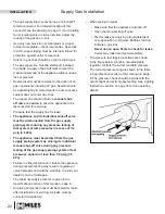
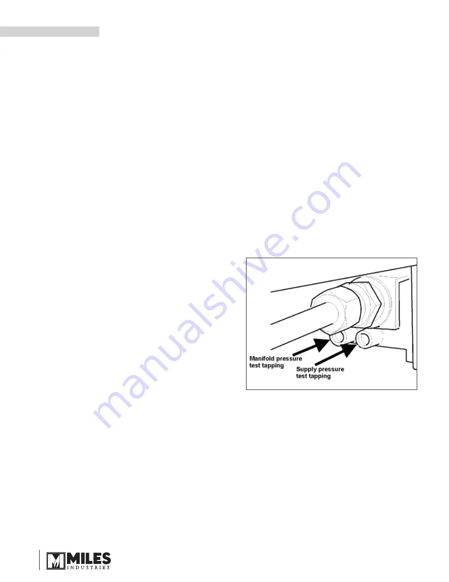
•  The pressure test tapping locations are shown 

in the 

fi

 gure below. A built-in non-adjustable 

regulator controls the burner manifold pressure. 
The correct pressure range is shown in the table 
in 

Specifi cations

 section of this manual on page 

8. The pressure check should be made with the 
burner alight and at its highest setting. See 

Lighting 

Instructions

 section on page 35 for full operating 

details.

INSTALLATION

Содержание Madrona MF28ILN

Страница 1: ...s supplier FS DV Gas Stove MF28ILN NG MF28ILP LPG HOT GLASS WILL CAUSE BURNS DO NOT TOUCH GLASS UNTIL COOLED NEVER ALLOW CHILDREN TO TOUCH GLASS Ce guide est disponible en fran ais sur demande This ap...

Страница 2: ...ed dealer Each Madrona is fully tested during the production process for your safety and comfort Your unit has been professionally installed by Dealer Name _______________________________________ Phon...

Страница 3: ...l contact with a hot surface A physical barrier is strongly recommended if there are young children or at risk individuals in the house Install an approved after market safety gate to keep toddlers yo...

Страница 4: ...upply Gas Installation 22 Ceramic Logs Installation 23 Window Refitting 24 Remote Control Initial Set up 24 Operation Check Aeration Settings Adjustment 25 Front Top Installation 25 Remote Control Han...

Страница 5: ...the flow of combustion and ventilation air Keep the front of the appliance CLEAR of all obstacles and materials for servicing and proper operation Due to the high temperature the appliance should be...

Страница 6: ...ensed professionals for the installation of hard wired carbon monoxide detectors Safety Warning Information a In the event that the side wall horizontally vented gas fueled equipment is installed in a...

Страница 7: ...ing requirements shall be satisfied by the manufacturer 1 The referenced special venting system instructions shall be included with the appliance or equipment installation instructions and 2 The speci...

Страница 8: ...re certified without deration for elevations up to 4 500 feet 1 370 m above sea level For elevations above 4 500 feet 1 370 m in USA installations must be in accordance with the current ANSI Z223 1 an...

Страница 9: ...ar 4 17 7 8 28 1 2 23 7 1 2 27 1 2 14 30 1 2 25 1 8 Center line Hearth Requirements This unit is approved for mounting directly on combustible wood flooring If installed directly on carpeting vinyl or...

Страница 10: ...Min 5 between combustible wall and rear of stove 17 7 8 28 1 2 40 1 2 minimum 43 1 2 minimum 26 maximum Alcove clearances Maximum 26 from wall for projection of combustible mantel or shelf 5 between c...

Страница 11: ...mbustible wall can be of any thickness up to the maximum horizontal run of vent pipe allowed for the particular installation 10 254 mm 10 254 mm Align the vent center to the center of the frame Import...

Страница 12: ...h wall without vertical rise Typical Venting Components See list of approved venting pipes and accessories on pages 37 38 Through wall with vertical rise Through roof Maximum pipe length 24 straight o...

Страница 13: ...inch per foot upwards in the direction of the exhaust flow 7 Co linear rear venting in existing chimney systems is limited to 40 feet vertical rise 8 Restrictors are not required for co linear install...

Страница 14: ...ed on laboratory tests The ideal restrictor position may vary slightly especially when the vent pipe length is near the limits of the acceptable configurations for each type of restrictors 50 75 Restr...

Страница 15: ...irectly above a sidewalk or paved driveway which is located between two single family dwellings and serves both dwellings 84 210 M Clearance under a verandah porch deck or balcony Only permitted if ve...

Страница 16: ...supplied in three 3 cartons In one carton is the engine In a second carton are the casting sides the top and the legs In a third carton are the casting front and base Unpack the cartons carefully We...

Страница 17: ...of fragile material and can easily be damaged Casting Base 1 Rough in the gas line and electrical wiring for a fan if any 2 Decide where the stove should be positioned to avoid moving it once all the...

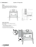
Страница 18: ...ail below Center the engine using the holes at front of the base as guidelines Casting Side Panels On the casting side panels release the top and bottom screws 1 Drop a hinge pin on the back corner of...

Страница 19: ...ets with the nuts and bolts provided Lighting Instructions Plate The lighting instructions plate is attached to the back of the engine and may have slid out of its slot Reposition the plate if this is...

Страница 20: ...G and then the burner 4 Using 3 screws fix the fan to the firebox bracket 5 Fix the fan control box bracket provided to the control box with 2 screws Fan control box position Fan control box bracket R...

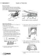
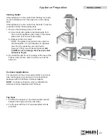
Страница 21: ...t necessary to separate them from the parts they are attached to However if they need to be manipulated BE CAREFUL not to damage them because their material is fragile 2 Re install through the vent op...

Страница 22: ...ressures in excess of 1 2 psig 3 5 kPa The appliance must be isolated from the gas supply piping system by closing its individual manual shut off valve during any pressure testing of the gas supply pi...

Страница 23: ...it on the right pin located on the rear log Rest its other end in the crook of the front right log 5 Identify the middle cross log It does not have a hole underneath Place its narrow end on the flat d...

Страница 24: ...batteries in the remote control receiver and handset The receiver is located left of the control valve under the burner module 2 With a sharp object press and hold the receiver s reset button until yo...

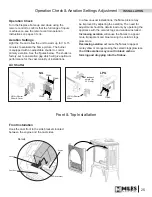
Страница 25: ...is factory set to an aeration gap which will give optimum performance for the vast majority of installations Operation Check Aeration Settings Adjustment Flashback shield for LPG only LPG Air Shutter...

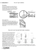
Страница 26: ...to the wall find a convenient location and use the hardware provided with the kit See the diagram for required hardware and configurations Note that the holder can be installed at the base of a light...

Страница 27: ...ompromising the strength of the glass An emulsion type cleaner is recommended Use a soft damp cloth to apply the cleaner Dry the glass with a soft dry preferably cotton cloth Most paper towels and syn...

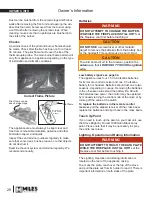
Страница 28: ...life Should the batteries lose power the control may be operated by manually turning the control knob at the valve or by turning off the valve at the switch To replace the batteries in the remote con...

Страница 29: ...efore operating your fireplace Handset and Wall Switch Press and hold the OFF button for a second either on the handset or the wall switch If the flames are on they go down and you hear the valve moto...

Страница 30: ...maximum flame height NOTE Before using the remote control system for the first time the receiver and the handset must be synchronized See the section Remote Control Initial Set up on page 24 of this...

Страница 31: ...t the hour Press small flame button to set the minute Press OFF or simply wait to return to MAN mode Double click large flame button Flame automatically goes to high fire HI will be displayed Manual M...

Страница 32: ...ete programming SETTING THE DAYTIME TEMPERATURE SETTING THE NIGHTTIME SETBACK TEMPERATURE Default Settings sun 23 C 74 F Default Settings moon OFF Press large flame button to increase Nighttime Setbac...

Страница 33: ...to TIMER moon while the time flashes Press large flame button to set the hour Press large flame button to set the hour Press small flame button to set the minutes Press small flame button to set the m...

Страница 34: ...u will need to reset the receiver to allow them to function together Contact your dealer for details No communication If there is no communication between the receiver and the handset for a period of...

Страница 35: ...WKH RRr If you smell gas STOP Follow B in the safety information above on this label If you don t smell gas go to the next step 3 AUTOMA7 1 7 21 J RFDWH WKH SLORW J LQVLGH RI UHER DW HIW DQG VLGH 21 2...

Страница 36: ...36 Wiring Diagram Optional Wall Switch Kit 1265WSK Connector Red Yellow GV60 Wiring Diagram INSTALLATION...

Страница 37: ...r Adapter 817VAK 4DSC V Co linear Flex Connector 46DVA ADF Co axial to Co linear Adapter 46DVA GCL TM 4CAA 4DCAB33 556CLA Co linear to Co axial Adapter 46DVA GK TM 4CTA 4DCAT33 Aluminum Flexible Liner...

Страница 38: ...onry Flashing TF 4MF Various Venting System Parts Wall Thimble 46DVA WT 4DT WT TM 4WT SV4RSM 4DWT Storm Collar 46DVA SC 4DT SC TM SC SV4AC 4DSC Decorative Plate 46DVA DC 4DT CS TM 4TR SV4PF 4DFPB Cath...

Страница 39: ...ir from other household equipment or appliances iii Damage due to chemicals dampness condensation or sulphur in the fuel supply lines which exceeds industry standards i This warranty does not cover gl...

Страница 40: ...se 4000926AH 4000926MJ 6 Fret 4000935AH 4000935MJ 2 Top Panel 4000928AH 4000928MJ 7 LH Side Panel 4000931AH 4000931MJ 3 Leg 4 4000929AH 4000929MJ 8 Infill Plate 4000927AH 4000927MJ 4 RH Side Panel 400...

Страница 41: ...066 18 Firebox Assembly 4000920AH 49 Inlet Connector 220K997 19 Rear Log Support 4001890 50 Inlet Pipe 030A224 20 Window Assembly 4000919 51 Pipe to Valve Connector 220K891 21 Heat Reduction Baffle 40...

Страница 42: ...ement Parts 8 9 10 11 50 75 12 13 14 16 17 20 21 66 18 22 65 NG LPG 23 24 27 25b 25a 28 37 29 31 36 32 33 34 35 38 39 40 42 41 43 44 45 46 47 48 52 53 51 54 49 55 56 64 63 62 62a 58 57 59 60 30 26a 26...

Страница 43: ...o Miles Industries Ltd Model MF28IL NG natural gas LPG propane Serial No Purchase date mm dd yyyy Home Owner Name Address City Province State Postal Code Zip Phone Email Address Store Type Fire shop H...

Страница 44: ...hut Thank you for choosing a Valor Product Postage needed Miles Industries Ltd 190 2255 Dollarton Highway North Vancouver BC V7H 3B1 Canada Fold here Online Warranty registration at www valorfireplace...

Отзывы: