
2 947995
CAUTION: To reduce the risk of electric shock,
Do not remove cover.
No user serviceable parts inside.
Refer servicing to qualified service personnel.
CAUTION
RISK OF ELECTRIC SHOCK
DO NOT OPEN
This symbol indicates that dangerous
voltage constituting a risk of electric
shock is present within this unit.
This symbol indicates that there are
important operating and maintenance
instructions in the literature accompanying
this unit.
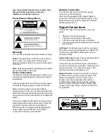
K1
K2
INPUTS
AUDIO
AUX
OUT
IN
AUDIO CC
+24V DC
may cause harmful interference in which case
the user will be required to correct the
interference at his own expense.
Precautionary Designations
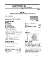
Mounting
The VIP-801 is designed for wall or table mounting.
Table:
Provided with the VIP-801 are four rubber
stick on feet. Peel these feet off their carrier
backing and place at the four corners of the bottom
of the unit.
Wall:
Using the template and instructions provided,
secure the VIP-801 to the wall.
Power Connections
The preferred method of powering a VIP-801 is via
a power over Ethernet switch meeting the 802.3af
specification.
If the rear panel barrel connector is used for power,
the preferred power supply is a Valcom VIP-324.
Make all required signal connections before
applying power to the unit. If powering via 802.3af,
make sure all signal connections via the back panel
are made then connect the VIP-801 to the Ethernet
switch.
If power is supplied via the barrel connector, make
sure all signal connections are secure. Attach the
unit to the network via the front panel RJ-45
Ethernet connector. Apply power by plugging the
power supply into the VIP-801 via the barrel
connector on the rear of the VIP-801.
Network Connection
The VIP-801 has one CAT-5 RJ-45 network
connector on the front panel.
Use one of the supplied CAT-5 patch cables to
connect the VIP-801 to an Ethernet switch. If the
Ethernet switch is 802.3af compliant the VIP-801
will draw power from it.
Signal Connections
The VIP-801 has 4 I/O connectors on the rear
panel:
•
RCA jack for AUX audio input
•
2 Pin screw terminal for audio output
•
6 Pin screw terminal for relay connections
•
4 Pin screw terminal for audio input and contact
closure input
AUX Input:
Local audio input is via the rear panel
RCA jack. Nominal input impedance is 600 Ohms.
Connect any compatible audio source using an
RCA patch cable.
Audio Channels:
Access to the networked audio is
via screw terminals on the rear panel.
The audio input and contact closure input share a
four pin screw terminal connection. Neither input is
polarity sensitive. The contact closure is on the
right two terminals and is labeled “CC”.
Relay Channels:
Access the two form C relays is
provided via a six pin screw terminal block. The
relays are labeled K1 and K2. Each relay is
brought out on three terminals. The common
contact is the middle terminal with the normally
closed contact on the left and the normally open
contact on the right. Relay contacts are rated for
1A @ 24VDC.
REAR VIEW


