background image


3  

TO REMOVE COVER
LOOSEN SCREW,
THEN ACTIVATE LATCH

PLASTIC
COVER

CIRCUIT BOARD
HOUSING ASSEMBLY

SNAP LATCH

METAL WALL
MOUNTING

PLATE

WIREWAY OPENING
TO WALL PLATE AND
JUNCTION BOX

WIRE TIE LOOP
WIRE TIE USED TO BUNDLE WIRES
ENTERING AND LEAVING TERMINAL AREA

SNAP LATCH
FOR COVER

.155 DIA. HOLES FOR MOUNTING TO
SINGLE OR DOUBLE GANG JUNCTION BOX
HOLE PATTERN MATCHES BOTH EURO 
AND US JUNCTION BOXES

1.5 x 2 WIRE ACCESS OPENING
TO JUNCTION BOX

BRACKET

LOCKING
SCREW


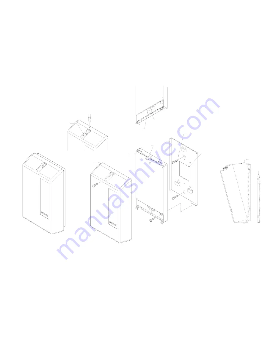
Mounting 

Remove the metal mounting plate from the rear of the V-9937 enclosure.  Using two #6 ¾ inch wood screws, 
mount the plate in a vacant space on the backboard with the telephone system common equipment.  

Both 

mounting holes must be utilized to insure secure mounting of the unit

.

  Provisions for mounting to a 

single or double gang junction box are provided.  See Figure 2 
 
Open the V-9937 enclosure to allow access to connections and option switches.  Slide the rear of the unit 
(contains the board) onto the mounting plate.  Lock enclosure to mounting plate with screw provided.  Make 
connections.  Replace cover and lock in place with #6 ½ inch screws provided. 


FIGURE 2 

MOUNTING 

EXPLODED VIEW 


Содержание V-9937

Страница 1: ...ain control Pop suppression Override capability using C O line position or PABX loop trunk port Low level input for background music typically 17dBm Automatic background music cutoff when the page por...

Страница 2: ...V 9937 Each instruction is preceded by a line Place a check on the appropriate line as the instruction is completed The instructions also include tests along the way to verify connections have been m...

Страница 3: ...ng Remove the metal mounting plate from the rear of the V 9937 enclosure Using two 6 inch wood screws mount the plate in a vacant space on the backboard with the telephone system common equipment Both...

Страница 4: ...ECTING BLOCK POINTS Wiring Arrangements 1 and 2 Refer to Figure 2 for location and numbering of connection block and Figure 3 for connecting block pin outs ___ 1 Unplug power supply ___ 2 Connect 24VD...

Страница 5: ...ack lead of horns NOTE Set speaker volume controls at approximately 1 2 volume during installation Volume Adjustment and Test Refer to Figure 4 for location of volume controls Test the system and adju...

Страница 6: ...nd pop suppression circuits Accessing this port will override inputs 2 and 3 Input 2 is transformer coupled to the V 9937 Ground must be applied to pin 3 for this input to operate provided from pin 18...

Страница 7: ...ch defective device within the warranty period provided that 1 inspection by Valcom Inc indicates the validity of the claim 2 the defect is not the result of damage misuse or negligence after the orig...

Страница 8: ...NOT MARKED OPTIONAL MUST BE COMPLETED V 9937 CONNECTING BLOCK FIGURE 5 WIRING CONNECTIONS FOR ARRANGEMENT 1 PAGE ONLY PAGE PLUS MUSIC 15 14 13 12 11 10 9 8 7 6 5 4 3 2 1 30 29 28 27 26 25 24 23 22 21...

Отзывы: