background image

9

947101

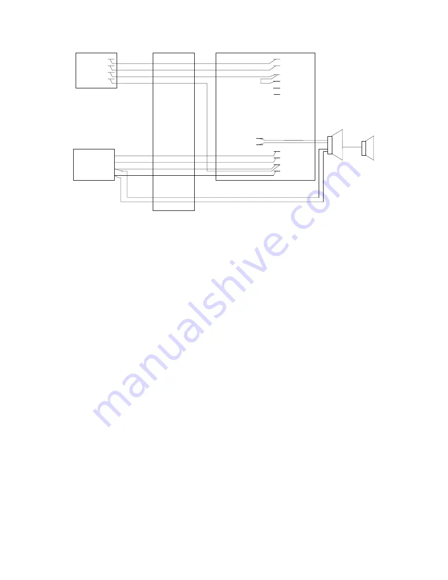
WIRING INSTRUCTIONS:

Place a check by each step as it is completed.

__  1.

Connect the Tip (W/BL) of the V-1101A to
Tip of your telephone system page port.

__  2.

Connect the Ring (BL/W) lead to Ring of
the page port.

__  3.

Add a strap on the V-1101A punchdown
block from H to DIR (W/O to W/G).

__  4.

Connect the V-1101A BG (V/S) lead to one
side of the page port dry contact closure.

__  5.

Connect the other side of the contacts to the
V-1101A H (W/O) lead.

__  6.

Connect Tip of the one-way amplified
speaker assemblies  to PG  (R/BR)  of the
V-1101A.

__  7.

Connect Ring of the speakers to OUT
(BR/R).

__  8.

Connect the GND terminals of the speakers
(black lead of horns) to the power supply
Ground ("+" or "B Ground").

__  9.

Connect the –24 Vdc lead of the speakers
(white  lead of horns)  to the  power supply
–24 Vdc terminal ("-" or "B Battery").

__ 10.

Plug in the power supply.

__ 11.

Test the system by dialing the telephone
system page access code or pressing the
page button and speaking into the handset:

__

(a) If you hear the page go to step 12.

__

(b) If you do not hear the page verify steps
1-10 have been performed properly and all
connections are good.  Also verify proper
telephone system configuration and
programming.  If you have programming
questions contact the telephone system
manufacturer.

__ 12.

Adjust the volume controls on the individual
speakers to the desired levels while paging.

__ 13.

If background music is to be provided:

__

(a) Connect   the  music  source  to  the  
V-1101A MT and MR (R/G and G/R).

__

(b) With the V-1101A idle adjust the music
source volume control to provide the desired
level at the speakers.

(W/BL)
(BL/W)
(W/O)
(O/W)

(V/BR)
(BR/V)
(V/S)
(S/V)

26

1

27
 2

49
24
50
25

TIP
RING

BLOCK

T
R

(W/BL)
(BL/W)

H
DIR (W/G)
MT (R/G)
MR (G/R)

(W/O)

PG (R/BR)

OUT(BR/R)

AG (V/BR)
AB (BR/V)
BG (V/S)
BB (S/V)

A GROUND
A BATTERY
B GROUND
B BATT

ONE-WAY
AMPLIFIED SPEAKER
ASSEMBLIES

FIGURE 6

PAGE PORT ACCESS

V-1101A

CONTACT

PUNCHDOWN

Содержание V-1101A

Страница 1: ...fidavits filed with the telephone company it will also be recorded in the system log kept by installation and maintenance personnel The local telephone company is to be notified of the FCC Registration Number when this intercom unit is installed SPECIFICATIONS Purpose To provide telephone system access to a single zone of one way paging Features Electronic key system line key access PABX loop trun...

Страница 2: ... Loop Trunk Card Valcom one way amplified speaker assemblies quantity and style determined by specific installation A 24 Vdc power supply size and quantity determined by number and style of speakers Operation Press the appropriate line key electronic key system or dial the appropriate trunk access code PABX You will immediately be connected to the paging speakers Make your announcement The V 1101A...

Страница 3: ...volume control The wiring of each arrangement is covered in the next section INSTALLATION General These instructions cover the installation procedures for the Valcom V 1101A and any associated equipment Please consult practices for other manufacturer s equipment if any other equipment is being used Refer to Figure 2 for connection block pinouts The following sections contain step by step instructi...

Страница 4: ...o a good Earth or Water Pipe ground 7 Power Test __ a Plug in power supply __ b Using a screwdriver momentarily short between the BFT W S and BFR S W leads of the V 1101A and listen for a relay to operate in the unit __ c If no relay is heard __ 1 Unplug power supply __ 2 Verify the V BR and V S pairs are properly connected at the punch down block and in the amphenol __ 3 Return to step 2 and veri...

Страница 5: ... R R BR BR R R S S R BK BL BL BK BK O O BK BK G G BK BK BR BR BK BK S S BK Y BL BL Y Y O O Y Y G G Y Y BR BR Y Y S S Y V BL BL V V O O V V G G V V BR BR V V S S V A B C D E F T R H SIG DIR CT2 CT2 BFT BFR A1 A1 A2 A2 MT MR PG OUT 24V DIR AG AB BG BB UNFILTERED 24VDC FILTERED 24VDC 24V START PAGE OUT MUSIC INPUT NORMALLY OPEN CONTACT NORMALLY OPEN CONTACT BATTERY FEED RING BATTERY FEED TIP NORMALLY...

Страница 6: ...4 Vdc lead of the speakers white lead of horns to the power supply 24 Vdc or B Battery __ 10 Plug in the power supply __ 11 Test the unit by connecting a lineman s test set across the V 1101A Tip and Ring __ a Go off hook and speak Your voice should come out the speakers __ b If you hear the page disconnect your test set and go to step 12 __ c If you do not hear the page 1 unplug the power supply ...

Страница 7: ...t by connecting a lineman s test set across the V 1101A Tip and Ring __ a Go off hook and speak Your voice should come out the speakers __ b If you hear the page disconnect your test set and go to step 12 __ c If you do not hear the page 1 unplug the power supply 2 go back to step 1 and recheck all your connections __ 12 Cross connect the tip W BL of the V 1101A to Tip of the paging line button of...

Страница 8: ...the speakers black lead of horns to the power supply Ground or B Ground __ 9 Connect the 24 Vdc lead of the speakers white lead of horns to the power supply 24 Vdc terminal or B Battery __ 10 Plug in the power supply __ 11 Test the system by pressing down the intercom button dialing the code for page access and speaking into the handset __ a If you hear the page go to step 12 __ b If you do not he...

Страница 9: ...ply __ 11 Test the system by dialing the telephone system page access code or pressing the page button and speaking into the handset __ a If you hear the page go to step 12 __ b If you do not hear the page verify steps 1 10 have been performed properly and all connections are good Also verify proper telephone system configuration and programming If you have programming questions contact the teleph...

Страница 10: ...rcom may be wired to use 10 Vac 18 Vac or 105 Vac for signaling The intercom signal must be momentary i e the signal must be present for approximately 1 second and then drop off A continuous signal will prevent the V 1101A from operating When connecting the V 1101A to a page port Figure 6 a Ground must be connected through the dry contact closure of the telephone system page card to both the Holdi...

Страница 11: ...o the installation Figure used and verify ALL connections Use a meter to verify the connections from the punchdown block to the amphenol If there is still no audio and you used Figure 5 Intercom Access connect a bell or buzzer to the V 1101A H and SIG leads Dial the page access number If the bell or buzzer does not ring then you are either not getting a page control from the intercom or you have c...

Страница 12: ...ucts to Valcom are prepaid 5 all units out of warranty are subject to a service charge The service charge will cover minor repairs Major repairs will be subject to additional charges for parts and labor This warranty is in lieu of and excludes all other warranties expressed or implied and in no event shall Valcom Inc be liable for any anticipated profits consequential damages loss of time or other...

Отзывы: