


4 947100
SYSTEM DESIGN
1A2, Dedicated Single Line Set, E-Key,
or PABX Paging
Telephone
System C.O.
Loop Start
Trunk Port
Valcom
Page
Control
Unit
T
R
Additional
Zones
(multi-zone
units only)
Speakers
Power Supply
(if required)
- and/or -
One or more dedicated
single line telephone(s)
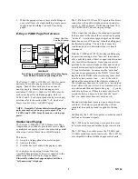
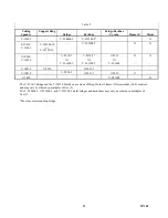
DIAGRAM 1
Block Diagram or Loop Start Trunk Port and/or Single Line
Telephone Access of a Valcom Page Control/Interface
To provide one-way paging on 1A2, E-Key PABX
Systems, or from one or more dedicated single line
telephones, you will need a page control unit, one-way
amplified speaker assemblies, and possible a power
supply. In most cases, page access will be via a line
button for 1A2, a loop trunk port for a PABX or
Electronic Key or via Tip and Ring on a singe line
telephone(s).
The control units may be any of the following.
1 zone
V-2000A
1 zone
V-2001A
3 zones w/all call
V-2003A
6 zones w/all call
V-2006A
9 zones w/all call
V-1109RTVA
24 zones w/all call*
V-2924A
*24 zone expansion
module ( up to 96 total)
V-2925A
The speakers may be any of those listed in Table 3 or
any other Valcom amplified speaker.or horn.
After you have selected the page control/interface and
the quantity and type of speakers for your system, use
Tables 1 and 2 to determine system power.
Add up the total Valcom power units (VPU) that will
be required. Subtract any power units being provided
by page controls featuring integrated power (2000
Series).
The remaining number of power units required will
determine the quantity and model(s) of power supply
required. Reference the next section,
"Valcom Power
Units"
.
Valcom Power Units
Each page control/interface, speaker and peripheral
device has been assigned a Valcom power unit (VPU)
value. Products that provide power, such as the 2000
Series page control/interfaces or power supplies, have
power unit values indicated with a plus (+) sign.
Products that consume power have power unit values
indicated with a minus (-) sign. Products that neither
require nor provide power are indicated by a VPU of
zero (0).
After you have chosen the page control interface,
speakers and accessories for your application, simply
add up all of the Valcom power units [indicated by a
minus (-)] for each item that requires power. This total
tells you how much power you need. If you have
chosen a 2000 Series control/interface, subtract the
total power units provided by this controller from your
previous total. If you come out even, or you have
power left over, you paging system is complete.
However, if you come out with more VPUs required
than provided, you will need additional power.
The additional power required will be provided by
adding one or more VALCOM power supplies as listed
in Table 4.
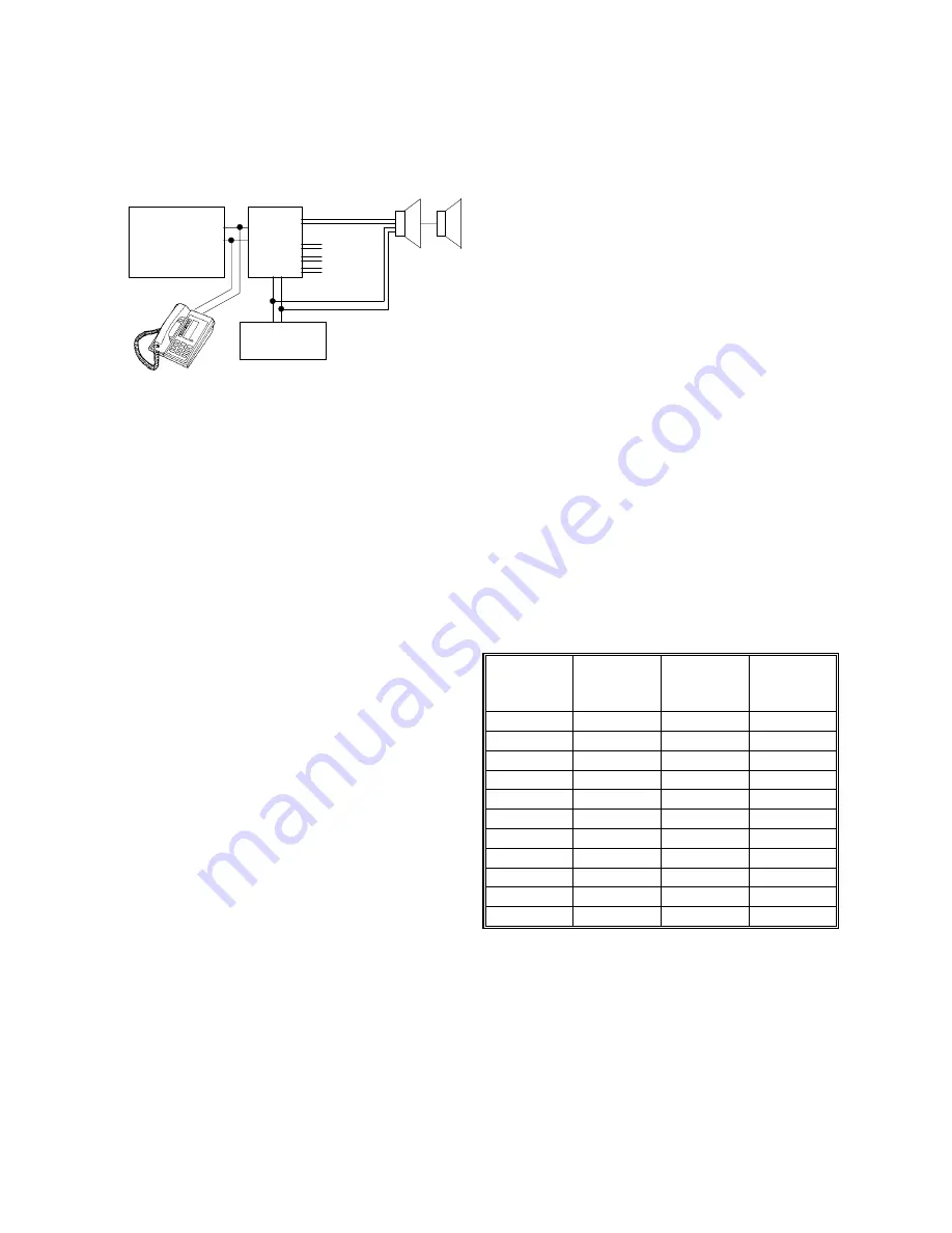
Table 4 - Valcom Power Supplies
Part #
Voltage
Maximum
Current
Valcom
Power
Units
VP-324 -24VDC 250
ma.
+6
VP-624B -24VDC 600
ma.
+12
VP-1124 -24VDC 1
amp
+20
VP-2024 -24VDC 2.0
amp
+40
VP-2124A -24VDC 2.0
amp
+40
VP-4024C -24VDC 4.0
amp
+80
VP-4124 -24VDC 4.0
amp
+80
VP-6124 -24VDC 6.0
amp +120
VP-12124 -24VDC 12
amp
+180
VP-2048C -48VDC 2
amp
N/A
VP-412A -12VDC 400
ma
N/A
There are several cases when more than one power
supply will be required:
1.
When the power required exceed the maximum
output of the power supplies available: Add
additional supplies as required.
2.
In large systems or systems with many horn
speakers: Locate separate power supplies near
groups of speakers. (Refer to Tables 8 and 10 for
guidelines concerning maximum allowable
distances for power runs.