4
947556
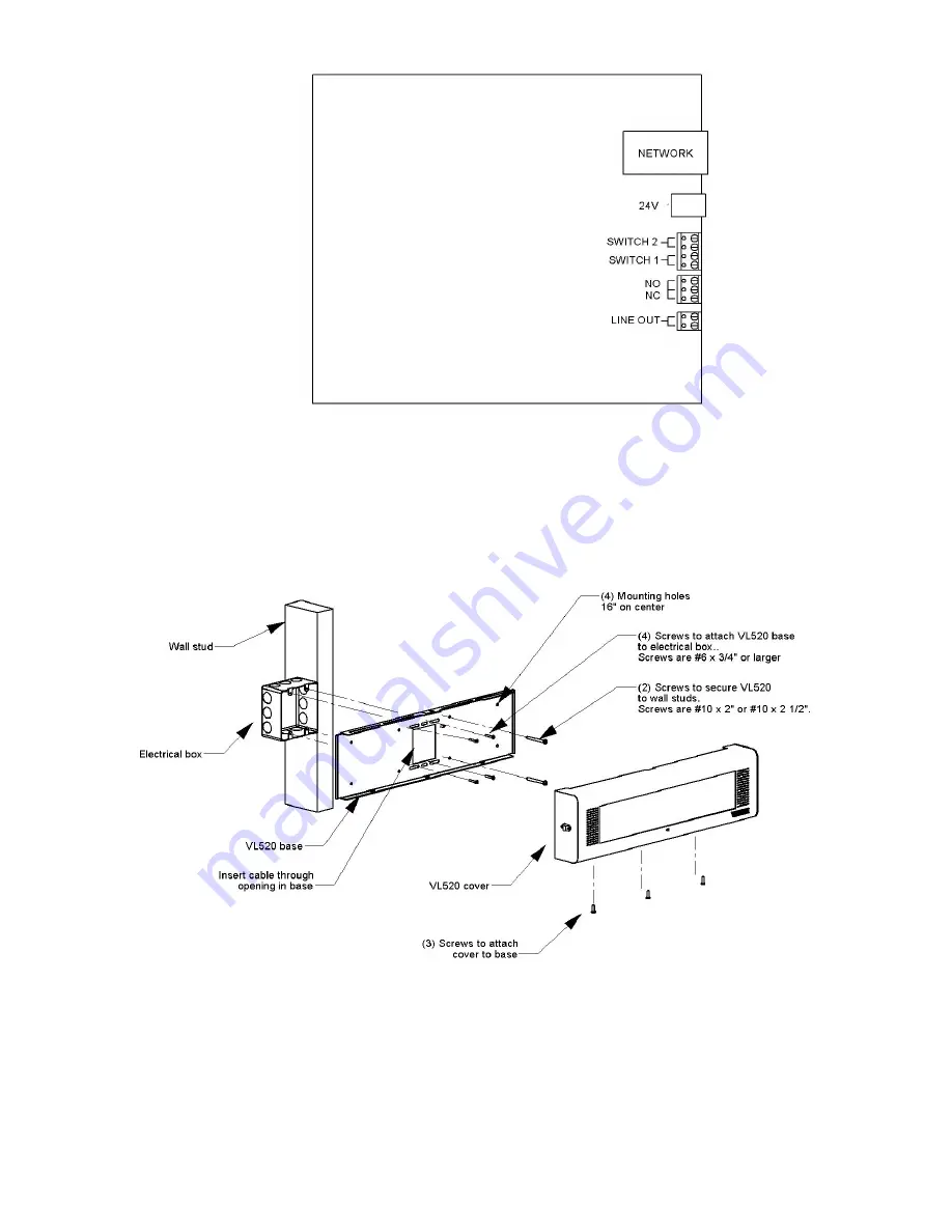
Figure 1. Network Connections
Figure 2. Mounting Diagram
Страница 1: ...r optional Call switch Relay connection for optional equipment Bright LED flashers that can be activated based on priority page Dimensions Weight 20 38 W x 5 5 H x 2 5 D 51 8cm W x 14 0cm H x 6 4cm D...
Страница 2: ...ccordance with the manufacturer s instructions Ne pas bloquer les ouvertures de ventilation Installer form ment aux instructions du fabricant 8 Do not install near any heat sources such as radiators h...
Страница 3: ...e factory default setting Other configuration items will not be affected Pressing the button continuously for greater than 20 seconds will perform a hard reset on the VL520 IC All of the configuration...
Страница 4: ...4 947556 Figure 1 Network Connections Figure 2 Mounting Diagram...