


8 Troubleshooting
69
8.1.4 Message
NO SENSOR
Cause
: The current in the cable to this sensor is below 20 mA. Normally this means
that there’s no sensor connected to the cable or that there’s no cable to the DTR. If
this message comes up while a sensor properly is connected, the most likely cause of
this message is a fault in the sensor. It is also possible that the cable is totally dead for
example if it is accidentally cut through.
See also Diagnostic LED LD1/LD3, Section 8.1.2 “Diagnostic LEDs”. The concentration
display will be a dashed line.
8.1.5 Message
NO SIGNAL
Besides the message, the concentration display will be a dashed line although a sensor
is connected.
Cause
: The current in the cable to this sensor is in the correct range 20–60 mA, but
no data is coming in from the sensor. This indicates that the Sensor processor card is
faulty.
See also Diagnostic LED LD1/LD3, Section 8.1.2 “Diagnostic LEDs”.
Action
: Replace the Sensor processor card.
8.1.6 Message
SHORT-CIRCUIT
The current in the cable to the sensor A/B exceeds 60 mA. First, the DTR attempts
for a short time to reconnect with the sensor in question. If the short-circuit persists,
the sensor in question is switched off completely to protect the Motherboard from
overheating.
See also Diagnostic LED LD2/LD4, Section 8.1.2, “Diagnostic LEDs”.
Note:
If two sensors are connected to the DTR, a short-circuit in one of the cables may
disturb the measurement of both sensors as DTR attempts to reconnect. The mea-
surement of the non-affected sensor returns to normal as soon as the short-circuited
sensor is switched off.
If the DTR detects a short-circuit that persists, the affected sensor is switched off to
prevent further damage. The message
SHORT-CIRCUIT
will stay on the screen until the
DTR is powered off and on.
See also Diagnostic LED LD2/LD4, Section 8.1.2, “Diagnostic LEDs”.
Cause and action
: The most likely cause of these messages is a problem in the cable
connecting the sensor in question to the DTR. Check that the cable is undamaged and
replace it if necessary, then turn the DTR off and back on.
Содержание K-PATENTS PR-23 AX Series
Страница 1: ...IM EN PR23 v 2 00 Instruction Manual Vaisala K PATENTS Process Refractometer PR 23...
Страница 2: ......
Страница 4: ......
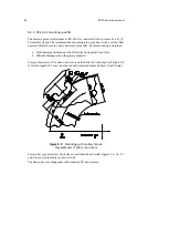
Страница 17: ...2 Inline refractometer sensor 7 2 2 2 PR 23 mounting guide...
Страница 26: ...16 PR 23 instruction manual...
Страница 29: ...4 Prism wash systems 19 Figure 4 1 A prism wash system for steam non sanitary...
Страница 30: ...20 PR 23 instruction manual Figure 4 2 A sanitary prism wash system for steam...
Страница 32: ...22 PR 23 instruction manual Figure 4 5 Wiring for a prism wash system for steam...
Страница 33: ...4 Prism wash systems 23 Figure 4 6 A prism wash system for high pressure water non sanitary...
Страница 34: ...24 PR 23 instruction manual Figure 4 7 A sanitary prism wash system for high pressure water...
Страница 35: ...4 Prism wash systems 25 Figure 4 8 Wiring for a prism wash system for high pressure water...
Страница 39: ...4 Prism wash systems 29 Figure 4 12 Mounting of the wash nozzle for Process refractometer PR 23 GP...
Страница 40: ...30 PR 23 instruction manual...
Страница 50: ...40 PR 23 instruction manual...
Страница 72: ...62 PR 23 instruction manual...
Страница 74: ...64 PR 23 instruction manual Figure 8 2 Motherboard PR 10600 and H1 interface card PR 10701 in detail...
Страница 113: ...9 Sensor specifications 103 WZ WZ WZ WZ WZ Figure 9 15 Mounting the sensor with a wfc flow cell...
Страница 151: ...9 Sensor specifications 141 Figure 9 38 Intrinsically safe wiring PR 23 IA according to WRG 362...
Страница 152: ...142 PR 23 instruction manual Figure 9 39 Intrinsically safe wiring PR 23 IF with STR according to WRG 478...
Страница 174: ...164 PR 23 instruction manual...
Страница 179: ...11 Safe Drive 169 11 3 3 Safe Drive steam wash system parts...
Страница 186: ...176 PR 23 instruction manual 11 4 2 Wiring Figure 11 9 PR 23 SD system wiring...
Страница 204: ...194 PR 23 instruction manual Figure 11 19 Markings on the retractor handle...
Страница 206: ...196 PR 23 instruction manual...
Страница 218: ...208 PR 23 instruction manual...
Страница 226: ...216 PR 23 instruction manual...
Страница 230: ...220 PR 23 instruction manual...
Страница 232: ...222...
Страница 238: ...228...
Страница 240: ...230...
Страница 242: ...232...
Страница 244: ...234...
Страница 246: ...www vaisala com...


