background image

Calibration and Adjustment

48

VAISALA

Calibration and Adjustment

HMT140 parameters are calibrated and adjusted using 
viewLinc.

To view calibration status:

On the 

Info

 tab, click 

Get

. This page will display calibra-

tion information including calibration date, calibrator, 
and next calibration due date.

Please refer to the Vaisala Veriteq viewLinc User’s guide for 
further information, or visit www.vaisala.com.
For calibration of 

HMP110D

 probes, refer to the 

supporting documentation available on the Vaisala 
website.

Battery Replacement

To replace the batteries and reset the battery meter of the 
HMT140:

1

Open the HMT140 case. Use your thumb to press and 
hold the release tab, located between the two glands, 
then pull the cover out and up with your fingers. See 
HMT140 Components Diagram on page 19 for location of 
release tab.

2

Turn the power switch off.

3

Remove the batteries by pulling them up firmly. If the 
battery does not come out easily, gently pull back on one 
of the battery holder tabs first.

Note:

Use only Vaisala supplied batteries, 
part #: 236318SP Vaisala 3.6V Lithium 
Thionyl Chloride batteries.

4

After replacing the batteries, press and hold the 
SERVICE button and turn the power switch on. The LED 
light will flash and the HMT140 will beep eight times.  

5

Release the SERVICE button. At this point, the battery 
meter is also reset.

CAUTION:

Remove batteries before shipping

Содержание HUMICAP HMT140

Страница 1: ...86 5 6 GUIDE Vaisala HUMICAP Humidity and Temperature HMT140 Wi Fi Data Logger M211488EN E...

Страница 2: ...sed to a third party without prior written permission of the copyright holder Translated materials and translated portions of multilingual documents are based on the original English versions In ambig...

Страница 3: ...0 Utility and Configuration Cable 11 CHAPTER 3 INSTALLATION 13 Mounting 14 Wall Mounting 14 Duct Installation 15 Optional Mounting Accessories 18 Wiring Diagrams 19 CHAPTER 4 SETUP AND OPERATION 23 Co...

Страница 4: ...vanced Options 39 Passwords 41 Set Up a New Channel 42 Find Additional Networks 42 Test Network Connectivity 43 Additional Program Parameters 44 CHAPTER 5 MAINTENANCE 45 Replacing the HUMICAP RH Senso...

Страница 5: ...tallation describes how to mount the HMT140 to a wall or duct and illustrates different wiring options Chapter 4 Setup and Operation contains the information you need to install and connect an HMT140...

Страница 6: ...nter http www vaisala com calibration Vaisala Headquarters Finland Vanha Nurmij rventie 21 01670 Vantaa FINLAND Industrial Instruments Phone 358 9 8949 2658 Fax 358 9 8949 2295 Japan Service Center 42...

Страница 7: ...hen touching removing or inserting any objects inside the equipment housing To make sure you are not delivering high static voltages Handle ESD sensitive components on a properly grounded and protecte...

Страница 8: ...negligent handling or installation or unauthorized modifications Please see the applicable supply contract or Conditions of Sale for details of the warranty for each product Regulatory Compliances The...

Страница 9: ...ation Cable The HMT140 Configuration Cable complies with part 15 of the FCC Rules Operation is subject to the following two conditions This device may not cause harmful interference This device must a...

Страница 10: ...Regulatory Compliances 6 VAISALA...

Страница 11: ...ns from ventilation to process control in demanding conditions For more information about other Vaisala relative humidity instruments please contact your Vaisala representative or visit www vaisala co...

Страница 12: ...ity RH Temperature T Switch Contact Voltage and Current Channel types are set at the factory during time of order Other wireless parameters can be changed at a later date using an HMT140 Configuration...

Страница 13: ...xternal Power Supply 236081SP HMP110D sensor protection Plastic grid filter DRW010522SP Plastic grid with membrane filter DRW010525 Stainless steel sintered filter HM46670SP Separate order form requir...

Страница 14: ...r code is written on the probe Optional Display The HMT140 is also available with an optional graphical 128x64 pixel resolution LCD display The display shows the measurement results of selected parame...

Страница 15: ...d See Figure 2 on page 15 For duct mounting Duct Installation Kits are available as accessories See Options and Accessories on page 9 To help you position the screws correctly use the Drilling Templat...

Страница 16: ...Introduction to the HMT140 12 VAISALA...

Страница 17: ...M211488EN E 13 CHAPTER 3 INSTALLATION This chapter provides the information you need to Mount the HMT140 on a wall or duct Connect the HMT140 to your network Review optional mounting accessories...

Страница 18: ...nt the HMT140 on a wall Note If mounting against a metal surface be sure to keep a minimum of 2 mm between the metal and the back of the HMT140 to ensure an uninter rupted radio signal 1 Open the HMT1...

Страница 19: ...ws could be also be used without sacrificing the ingress protection IP class of the enclosure Duct Installation The duct installation kit includes a plastic pipe with a flange Vaisala part 215619 To i...

Страница 20: ...16 for details Figure 3 Probe Installation The following numbers refer to Figure 3 1 Tension screw Distance L can be adjusted and locked in place with the tension screw Probe Assembly with Duct Instal...

Страница 21: ...3 HMP110D assembled in duct installation kit plastic pipe To attach the probe assembly to the duct 1 Drill the holes for the duct installation kit as follows Use a 24 mm drill bit to drill a hole in...

Страница 22: ...ld the HMP110D probe in a through wall installation Note The coaxial silicone plug that is delivered with the flange is not suitable for use with the probe cable of the HMT140 Figure 7 Optional Probe...

Страница 23: ...Clamp CAUTION Attaching the probe mounting clamp to a con ductive wall material should be avoided since the potential galvanic connection to the power supplies and uncontrolled earth current loops cou...

Страница 24: ...Wiring Diagrams 20 VAISALA Figure 10 RTD Wiring Diagram Figure 11 RTD and Boolean Wiring Diagram Figure 12 Boolean Wiring Diagram...

Страница 25: ...Wiring Diagrams M211488EN E 21 Figure 13 Voltage Wiring Diagram Figure 14 Current Wiring Diagram Figure 15 Power Supply Wiring Diagram...

Страница 26: ...Wiring Diagrams M211488EN E 23...

Страница 27: ...P AND OPERATION This chapter will guide you during the setup of your HMT140 with your network parameters Here you will find the information you need to Configure the HMT140 Operate the HMT140 Customiz...

Страница 28: ...configure the HMT140 the HMT140 Utility software must be installed on the PC The driver is compatible with Windows 2000 Windows XP Windows 7 and Windows Server 2003 To install the HMT140 Utility 1 Di...

Страница 29: ...ure that the HMT140 Configuration Cable is not connected to the HMT140 6 Turn the power switch on the HMT140 to the ON position and wait for the setup process to complete about five seconds LED light...

Страница 30: ...ct the end of the Configuration Cable labelled USB Wi Fi Programmer to the 4 pin HMT140 CONFIG header 6 On the HMT140 Setup tab click Retrieve to identify the HMT140 The bottom left status bar will in...

Страница 31: ...settings 10 Enter the Destination IP address name and port number of the host these are the Vaisala viewLinc server settings to which the HMT140 will send information Note If you do not know what info...

Страница 32: ...s are installed Vaisala part 236318SP 2 Turn on the HMT140 and wait five seconds to ensure the startup process completes 3 Plug the USB connector on the HMT140 Configuration Cable to the computer if i...

Страница 33: ...0 will log I O into the log buffer Note When setting up a new HMT140 you can click Retrieve to view current settings Enable Beeper Select the option to enable or disable the button control of the Beep...

Страница 34: ...hat per centage of battery life remaining you want the HMT140 to stop transmitting data to the host to save battery power Once this threshold is reached the HMT140 functions normally except it will no...

Страница 35: ...ng the model name and channel type Note Check with your network administrator before making changes To modify your HMT140 name and Channel descriptions 1 Complete steps 1 to 6 in the procedure Modify...

Страница 36: ...ly assigned and the HMT140 will cache this IP address Failed the HMT140 could not obtain the IP settings IP Address Current IP address If 0 0 0 0 then no IP address has been assigned Subnet Mask Curre...

Страница 37: ...to determine the signal strength Channel This is the channel found during the Channel Auto Find feature or the channel set in the Setup page If the HMT140 cannot find a channel when in Auto Find mode...

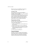
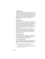
Страница 38: ...when it is entering an alarm state Transmission of Data The HMT140 will go through the following steps in order to connect to a network and deliver data 1 Associates with the network 2 HMT140 authent...

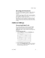
Страница 39: ...alarm state Refer to the Vaisala Veriteq viewLinc User s Guide for information about alarm settings Additional Settings Change Input Output Scale If you want your HMT140 to provide more meaningful ou...

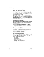
Страница 40: ...ved Settings Both the Saved Settings and the Saved Network Settings can be deleted to help keep the list of saved settings easier to view and or manage On the File menu select Delete Sensor Setup or D...

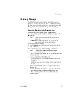
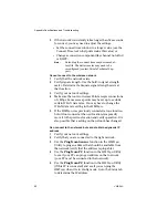
Страница 41: ...must be reset to recognize the new battery status To view battery life remaining On the Status tab view the batter meter status in the Est Life field To reset the battery meter after installing new ba...

Страница 42: ...xpected battery life To perform the test see page 43 Note If the average connection time is more than five seconds the HMT140 may not connect consis tently and the battery may be exhausted before the...

Страница 43: ...t to the network with one second between connection attempts You can then view Number of connection attempts Last connect time Average minimum and maximum connect times History of connect attempts dis...

Страница 44: ...attempt to contact the host DNS Caching When this option is selected the HMT140 will cache the IP address that results from the DNS lookup of the Destination hostname The HMT140 will keep the destina...

Страница 45: ...the Options menu select Advanced Options 4 On the Advanced Options window check Enable use of passwords in HMT140 then click OK 5 To set the password for the first time Leave the Current Password fiel...

Страница 46: ...Channel Auto Find search channels to more than 3 channels This will have an effect on the HMT140 s range and battery life For Wi Fi 802 11g radio mode the HMT140 can search all channels with minimal...

Страница 47: ...clicked the HMT140 will use either the IP address in the IP Address field or the current address in the Destination IP field in the Setup tab and ping that specified address Once the ping operation is...

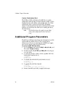
Страница 48: ...Program Parameters The HMT140 Utility stores all program information in an INI text file HMT140Utility INI You can use this file for reference and if you are updating several HMT140 loggers save time...

Страница 49: ...des information to help you provide basic in house maintenance of the HMT140 including Instructions for replacing the HUMICAP RH sensor Instructions for removing and fastening probes Calibration and a...

Страница 50: ...110D Series User s Guide for complete instructions Removing and Fastening the Probe Fixed Probe Model To remove and replace a fixed probe 1 Loosen the metal locking bushing by carefully turning it cou...

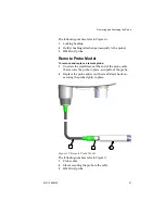
Страница 51: ...To remove and replace a remote probe 1 Unscrew the small sleeve at the end of the probe cable that secures the probe in place and pull out the probe 2 Replace the probe and screw the small sleeve back...

Страница 52: ...the HMT140 1 Open the HMT140 case Use your thumb to press and hold the release tab located between the two glands then pull the cover out and up with your fingers See HMT140 Components Diagram on pag...

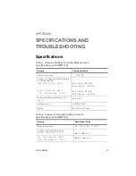
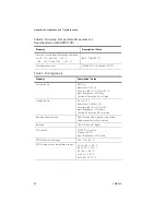
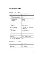
Страница 53: ...2 104 F at 40 0 C and 40 80 C 40 32 F and 104 176 F 1 7 RH 0 90 RH 2 5 RH 90 100 RH 3 0 RH 0 90 RH 4 0 RH 90 100 RH Factory calibration uncertainty at 20 C 68 F 1 5 RH Humidity sensor HUMICAP 180R Sta...

Страница 54: ...x Voltage inputs 0 5 V 0 10 V Resolution 0 0034 F S Accuracy 0 15 F S at 25 Input Impedance 37K Ohms Overload Protection 50 volts max Boolean Contact inputs Open Closed with magnetic reed switch cable...

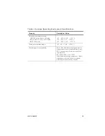
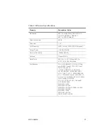
Страница 55: ...probe 40 60 C 40 140 F 20 60 C 4 140 F 40 80 C 40 176 F Storage temperature range 50 70 C 58 158 F Electomagnetic compatibility EN 61326 1 2006 Electrical equipment for measurement control and labora...

Страница 56: ...Appendix Specifications and Troubleshooting 54 VAISALA HMT140 Dimensions Fixed Probe...

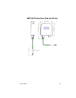
Страница 57: ...M211488EN E 55 HMT140 Dimensions Remote Probe...

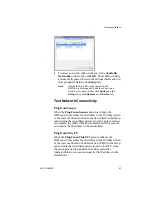
Страница 58: ...Connections Screw terminals HMP110D Probe interface 26 AWG 20 AWG 4 pin M8 female panel connector HMP110D Probe cable lengths 3 m 5 m cables can be cascaded up to maximum of 10 m RTD Temperature Senso...

Страница 59: ...ertifications FCC U30 G2M5477 FCC Part 15 Sub part B 2008 Class B FCC CRF Title 47 Part 15 Subpart C IC 8169A G2M5477 IC RSS 210 CE EU ID 0681 ETSI EN301 489 1 V1 8 1 489 17 V2 1 1 ETSI EN300 328 V1 7...

Страница 60: ...de the HMT140 remains in a low power state but will turn on connect transmit a UDP packet and then go back to the low power state when it is ready to transmit Signal Strength The HMT140 works best wit...

Страница 61: ...T140 has Auto Find for the channel and the right channels have been selected for Auto Find channels Some access points will move between three channels typically 1 6 and 11 The HMT140 Utility will wor...

Страница 62: ...may be set up to exclude certain WLAN data rates You may have to change the WLAN data rate setting in the HMT140 5 If the HMT140 was previously connected at one location but will not connect at the n...

Страница 63: ...default will not route broadcast traffic 5 If the host will respond to ping requests use the Ping from Sensor function in the Utility to have the HMT140 ping the host Use the Ping from PC feature if t...

Страница 64: ...he connect time window to a longer value use the Connect Time tool to help determine this value or change a connection component like channel AutoFind or DHCP Note Extending the Connect Window may cau...

Страница 65: ...and connect again 4 Disconnect the cable from the HMT140 and then disconnect the cable from the PC Wait 30 seconds Insert cable back into PC and into the HMT140 5 Reboot your computer 6 Use an extern...

Страница 66: ...4 VAISALA Workaround 1 Use Dynamic IP and have DCHP Caching turned off If the IP address is static or the DHCP Caching is enabled these routers will not forward the HMT140 s UDP data packet 2 Replace...

Страница 67: ...ig setup mode 33 configuration cable 24 connecting HMT140 to your network 35 HMT140 to your PC 24 connection performance 38 Current Wiring Diagram 21 D deleting settings 36 device components 10 diagra...

Страница 68: ...retrieving 36 saving 31 P passwords recording 41 passwords about 44 Power Supply Wiring Diagram diagrams power supply wiring 21 probe removing fastening 46 47 Probe Assembly with Duct Installa tion Ki...

Страница 69: ...mode 34 transmitter type viewing 26 U USB cable 24 V viewing calibration status 48 transmitter type 26 Voltage Wiring Diagram 21 W wall mounting 14 wiring boolean diagram 20 current diagram 21 power s...

Страница 70: ...www vaisala com M211488EN...

Отзывы: