Wiring Diagrams
M211488EN-E
19
Installing the entire probe in the measurement environment
prevents heat conduction to the sensor, and is the
recommended installation method.
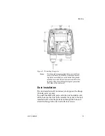
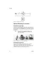
Figure 8: Optional Probe Mounting Clamp
CAUTION:
Attaching the probe mounting clamp to a con-
ductive wall material should be avoided, since
the potential galvanic connection to the power
supplies and uncontrolled earth current loops
could cause measurement errors or even dam-
age to an HMT140 (not the HMT141
).
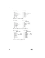
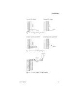
Wiring Diagrams
The following figures outline the components, wiring and
connections of the HMT140.
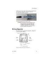
Figure 9: HMT140 Components Diagram
Содержание HUMICAP HMT140
Страница 1: ...86 5 6 GUIDE Vaisala HUMICAP Humidity and Temperature HMT140 Wi Fi Data Logger M211488EN E...
Страница 10: ...Regulatory Compliances 6 VAISALA...
Страница 16: ...Introduction to the HMT140 12 VAISALA...
Страница 26: ...Wiring Diagrams M211488EN E 23...
Страница 56: ...Appendix Specifications and Troubleshooting 54 VAISALA HMT140 Dimensions Fixed Probe...
Страница 57: ...M211488EN E 55 HMT140 Dimensions Remote Probe...
Страница 70: ...www vaisala com M211488EN...


