For the competent person
Installation instructions
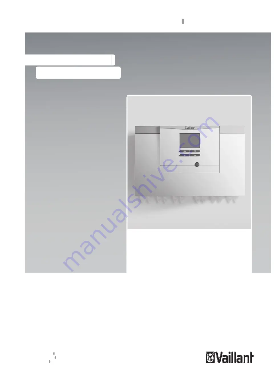
Heat pump control module
VWZ AI VWL X/2 A
UK
Installation instructions
Publisher/manufacturer
Vaillant GmbH
Berghauser Str. 40
D-42859 Remscheid
Telefon 021
91
18
‑
0
Telefax 021
91
18
‑
28 10
[email protected]
www.vaillant.de