Vaillant ecoFIT sustain Series Скачать руководство пользователя страница 10

10

Installation and maintenance instructions ecoFIT sustain 0020230529_06
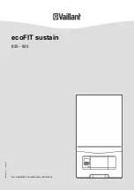
5.3

Functional elements: Combi boiler

15

12

11

10

8

9

7

5

6

4

3

2

1

18

17

20

19

14

16

13

1

Electronics box

2

Pressure relief valve for
the heating circuit

3

Plate heat exchanger

4

Condensate trap

5

Flue pipe

6

Pressure sensor

7

Flue gas analysis point
(for the rear air/flue
connection)

8

Ignition transformer

9

Gas valve assembly

10

Air intake pipe

11

Fan/gas-air mixture

12

Supply air test point
(for the upper air/flue
connection)

13

Flue gas analysis point
(for the upper air/flue
connection)

14

Primary heat exchanger

15

Heating expansion
vessel

16

Purging hose

17

Volume flow sensor

18

Heating pump

19

Bypass

20

Diverter valve

5.4

Safety Devices

5.4.1

Electrical Supply Failure

The boiler will not work without an electrical supply. Normal
operation of the boiler should resume when the electrical
supply is restored.

Reset any external controls, to resume normal operation of
the central heating.

If the boiler does not resume normal operation press the
reset button. If the boiler does not resume normal operation
after this call your Installation/Servicing company or Vaillant
service.

5.4.2

Overheating Safety

The boiler software is designed to recognise the potential for
an overheat lockout and will shutdown before this happens.
To restart the boiler, press the reset button on the boiler
interface.

If the boiler fails to resume normal operation and all external
controls are calling for heat, then call your Installation/ Servi-
cing company or Vaillant service.

5.4.3

Frost protection

The appliance has a built in frost protection device that pro-
tects the boiler from freezing. With the gas and electric sup-
plies ON and irrespective of any room thermostat setting, the
frost protection device will operate the pump when the tem-
perature of the boiler water falls below 12 °C.

A timer is used so that the temperature can be checked peri-
odically. After 10 minutes the pump will be stopped if the
temperature is higher than 10 °C or has already reached
35 °C. The burner will activate if the boiler temperature does
not reach 10 °C after 30 minutes or at any time if the temper-
ature drops to 5 °C.

The burner will switch off when the temperature reaches
35 °C.

5.4.4

Condensate Drain Blockage

As a safety feature the boiler will stop working if the con-
densate drain becomes blocked. During freezing conditions
this may be due to the forming of ice in the condense drain
external to the house. Release an ice blockage by the use
of warm cloths on the pipe. After pressing reset the boiler
should restart.

Содержание ecoFIT sustain Series

Страница 1: ...en Installation and maintenance instructions ecoFIT sustain 825 835 0020230529_06 20 10 2020...

Страница 2: ...cient water pressure 25 9 6 Flushing the heating installation for the first time cold 25 9 7 Filling and purging the heating installation 25 9 8 Filling the domestic hot water circuit 26 9 9 Checking...

Страница 3: ...y direct use in industrial or commercial processes Any use other than those described in these instructions and any use that goes beyond what is described here 1 2 Qualification The person carrying ou...

Страница 4: ...ercially available soft soap to aid installa tion 1 3 3 Electricity The power supply terminals L and N remain live even if the unit main switch is switched off To prevent electric shocks proceed as fo...

Страница 5: ...t 1 3 10 Safety devices Install the necessary safety devices in the installation 1 4 Regulations directives laws standards Observe the national regulations stand ards directives ordinances and laws 1...

Страница 6: ...aillant group com Spares Enquiries Telephone 01773 596 615 To register your Vaillant appliance visit https self service vaillant co uk warranty registration Vaillant is a licensed member of the Benchm...

Страница 7: ...gas mass rate in hot water handling mode at P max 11 6 g s 13 8 g s 16 1 g s Flue gas temperature 80 C 60 C at P max 60 77 86 Flue gas temperature 80 C 60 C at P min 55 55 56 Flue gas temperature 50...

Страница 8: ...volume pH value between 3 5 and 4 0 at 50 30 C 1 84 l h 1 84 l h 1 84 l h P heating at nominal flow T 20 K 0 025 MPa 0 250 bar 0 025 MPa 0 250 bar 0 018 MPa 0 180 bar Technical data Domestic hot water...

Страница 9: ...with serial number Serial number For quality control purposes 3rd and 4th digits year of production For quality control purposes 5th and 6th digits week of production For identification purposes 7th...

Страница 10: ...y The boiler software is designed to recognise the potential for an overheat lockout and will shutdown before this happens To restart the boiler press the reset button on the boiler interface If the b...

Страница 11: ...w and return 1 Domestic hot water connection service valve 1 Gas stopcock 2 Connection pipe heating flow and return 1 Cold water connection pipe 1 Domestic hot water connection pipe 1 Gas pipe 1 Drain...

Страница 12: ...sequence the heat loss from the appliance casing during operation is very low Compartment ventilation is not required as the products are only certified and can only be fitted with a concentric flue s...

Страница 13: ...lding material Vertical flue clearance to combustible building material 500 mm 1 500 mm J Above below and either side of an opening door air vent or opening window 300 mm K Diagonally to an opening do...

Страница 14: ...nce from pluming depending on site conditions Terminals must be positioned so to avoid combustion products entering the building Support the flue at approximately one metre intervals and at a change o...

Страница 15: ...50 mm clearance from any part of the terminal and be central over the terminal The guard should be similar to that shown in the figure 6 6 3 3 Vertical Concentric Flue 60 100 mm or 80 125 mm C33 type...

Страница 16: ...of material damage caused by mech anical deformation Removing both side sections may cause mechanical distortion in the product which may cause damage to the piping for ex ample and potentially resul...

Страница 17: ...tightness of the gas valve assembly using a pressure of 11 kPa 110 mbar 7 2 Descaling the water Scale deposition increases as the water temperature in creases Descale the water as required 7 3 Check...

Страница 18: ...move all burrs from inside of cut pipe work and avoid excessive adhesive which may trap small pockets of water close to the pipe wall which can freeze and build into a larger ice plug For any installa...

Страница 19: ...ferred option must not terminate in rain water drain 7 6 1 6 Internal termination downstream of sink waste 100mm 32mm 22mm 3 m Open end of pipe direct into gulley below ground level but above water le...

Страница 20: ...Cable route 2 1 230V 24V eBus 1 230 V cable route 2 24 V cable or eBUS cable route 7 8 3 General information about connecting cables Caution Risk of material damage caused by incor rect installation M...

Страница 21: ...t should be identified as to its use 6 Provide one common power supply for the boiler and for the corresponding control Power supply Single phase 230 V 50 Hz Fuse protection 3 A 7 Open the electronics...

Страница 22: ...ctions ecoFIT sustain 0020230529_06 Condition When connecting a control 230 V 30 mm N L X1 230V RT Connect the control to the main plug BUS RT B off Burner off RT 24V BUS Remove the bridge from the 24...

Страница 23: ...he Anti legionella measures in order to comply with the applicable regulations regarding legionella prevention Set the hot water temperature Condition Water hardness 3 57 mol m Water temperature 50 8...

Страница 24: ...ot stipulate more stringent requirements the following applies You must treat the heating water in the following cases If the entire filling and supplementary water quantity dur ing the operating life...

Страница 25: ...alls below 0 05 MPa 0 5 bar the value flashes in the display If the water pressure falls below 0 03 MPa 0 3 bar the product switches off The display shows 0 0 MPa 0 0 bar Fault F 22 is stored in the f...

Страница 26: ...e gas recirculation using the air analysis point 3 Use a flue gas analyser 4 If you discover unusual levels of CO or CO 2 in the sup ply air search for the leak in the flue system or for signs of flue...

Страница 27: ...stopcock 1 Remove the pressure gauge and retighten the sealing screw 2 for the measuring nipple Open the gas stopcock 1 Check the test nipple for gas tightness Install the front casing Page 16 Reset...

Страница 28: ...tting the burner anti cycling time 1 Navigate to diagnostics code D 002 in the installer level and confirm by pressing 2 Set the burner anti cycling time and confirm by pressing TFlow tar get C Set ma...

Страница 29: ...hot water temperature 50 3 Descale the water as required 11 Handing over to the end user At the time of commissioning complete all relevant sec tions of the Benchmark commissioning checklist located...

Страница 30: ...9 2 1 0 vol CO at full load 250 ppm 250 ppm CO CO 0 0031 0 0031 The value is OK The value is not OK you cannot start up the product Set the CO content Page 30 12 5 Setting the CO content Condition Th...

Страница 31: ...rd ing to the following sections 13 Install the two new burner seals 12 7 Cleaning the heat exchanger 1 1 Protect the open electronics box from spraying water 2 Clean the ribs of the heat exchanger 1...

Страница 32: ...trap 2 12 11 Cleaning the strainer in the cold water inlet 1 Close the main cold water supply line 2 Drain the product on the domestic hot water side 3 Remove the connector from the connection for th...

Страница 33: ...e last 10 fault messages are stored in the fault memory Call up the installer level Page 23 Navigate to the fault codes The number of faults that have occurred is shown in the display and the faults t...

Страница 34: ...32 13 5 3 Replacing the heat exchanger 1 Remove the front casing Page 16 2 Remove the gas air mixture unit Page 30 1 A B 3 Remove the gas pipe 1 1 2 3 2 4 A B 4 Remove the temperature sensor 3 5 Remo...

Страница 35: ...sel to the water connec tion To do this use a new seal 8 Attach the support plate using both screws 9 Fill and purge the product Page 25 and if required the heating installation 13 5 6 Replacing the P...

Страница 36: ...Replace the pressure sensor 1 2 1 Pull out the plug 2 Remove the clip 1 3 Remove the pressure sensor 2 4 Install the new pressure sensor 5 Reattach the clip 1 13 6 Checking the product for leak tightn...

Страница 37: ...ually 10 If the gas flow rate lies outside of the tolerances specified in these in structions eliminate the fault in accordance with the regulations and the current technology Annually 11 Check the ge...

Страница 38: ...for the product in question Dia gnostics code Parameter Values Unit Increment select explanation Default set ting Own setting Min Max d 00 Heating maximum output kW The maximum heating output varies...

Страница 39: ...age 2 pump flow overrun stage 1 1 Heating mode and pump run overrun stage 1 domestic hot water mode stage 2 2 Automatic heating mode pump rin overrun stage 1 do mestic hot water mode stage 2 3 Stage 2...

Страница 40: ...temperat ure Current value Not adjustable d 41 Heating return temper ature Current value Not adjustable d 43 Heat curve 0 2 4 0 1 1 2 Adjustable d 45 Value for the base point of the heat curve 15 30...

Страница 41: ...ng time in do mestic hot water mode Current value h Running time Display value x 100 Not adjustable d 82 Number of burner igni tions in heating mode Current value Number of ignitions Display value x 1...

Страница 42: ...stic hot water mode Fan prerun S 22 Domestic hot water mode Pump prerun S 23 Domestic hot water mode Burner ignition S 24 DHW mode Burner on S 25 DHW mode Pump fan overrun S 26 DHW mode Fan overrun S...

Страница 43: ...hutdown Temperature rise too fast Pump blocked insufficient pump output air in product system pressure too low non return valve blocked incorrectly installed F 25 Safety shutdown Flue gas temperature...

Страница 44: ...afety cut out feedback does not match the gas valve assembly feedback F 77 Fault Condensate or smoke No response flue non return flap defective F 78 Interruption to DHW outlet sensor at external contr...

Страница 45: ...RT 230Vac X35 4 1 3 2 eBUS RT 24V Burner off X106 1 3 4 1 3 3 1 2 M 1 3 4 6 1 2 3 M 5 4 2 1 2 1 2 1 N L L 24V 230V 24V 230V 2 7 8 9 10 12 11 1 4 3 5 6 14 13 1 Main PCB 2 Interface PCB 3 Timer 4 Tempe...

Страница 46: ...30Vac 4 3 1 2 eBUS RT 24V Burner off X106 X35 1 3 4 1 3 3 1 2 M 1 3 4 6 1 2 3 M 4 3 2 1 5 4 2 1 5 6 7 8 2 1 2 1 N L L X35 24V 230V 24V 230V 2 7 8 9 10 12 11 1 4 5 6 14 13 3 1 Main PCB 2 Interface PCB...

Страница 47: ...mer and they should be made aware it is ultimately their responsibility to register with the manufacturer within the allotted time period It is essential that the boiler is serviced in line with the m...

Страница 48: ...t left at factory settings Yes No If no what is the maximum central heating output selected kW Dynamic gas inlet pressure mbar C Central heating return temperature C System correctly balanced rebalanc...

Страница 49: ...LER delete as appropriate Date Engineer name Company name Telephone No Gas Safe registration No Max rate CO ppm CO CO CO Min rate CO ppm CO CO CO undertaken in accordance with manufacturers instructio...

Страница 50: ...LER delete as appropriate Date Engineer name Company name Telephone No Gas Safe registration No Max rate CO ppm CO CO CO Min rate CO ppm CO CO CO undertaken in accordance with manufacturers instructio...

Страница 51: ...specify how to set boiler to minimum rate contact Technical Helpline for advice CHECK CO AND COMBUSTION RATIO AT MINIMUM RATE With boiler still set at minimum rate insert analyser probe into flue gas...

Страница 52: ...hecking 17 Gas setting 26 Gas air mixture removing 30 Guarantee and Customer Service 6 H Handing over to the end user 29 Heat exchanger cleaning 31 Heat exchanger replacing 34 High efficiency pump 28...

Страница 53: ......

Страница 54: ......

Страница 55: ......

Страница 56: ...lisher manufacturer Vaillant GmbH Berghauser Str 40 D 42859 Remscheid Tel 492191 18 0 Fax 492191 18 2810 info vaillant de www vaillant de These instructions or parts thereof are protected by copyright...

Отзывы: