0020277262_02 ecoFIT sustain Installation and maintenance instructions
27
Additives for frost protection intended to remain
permanently in the installation
–
Adey MC ZERO
–
Fernox Antifreeze Alphi 11
–
Sentinel X 500
▶
If you have used the above-mentioned additives, inform
the end user about the measures that are required.
▶
Inform the end user about the measures required for frost
protection.
9.3
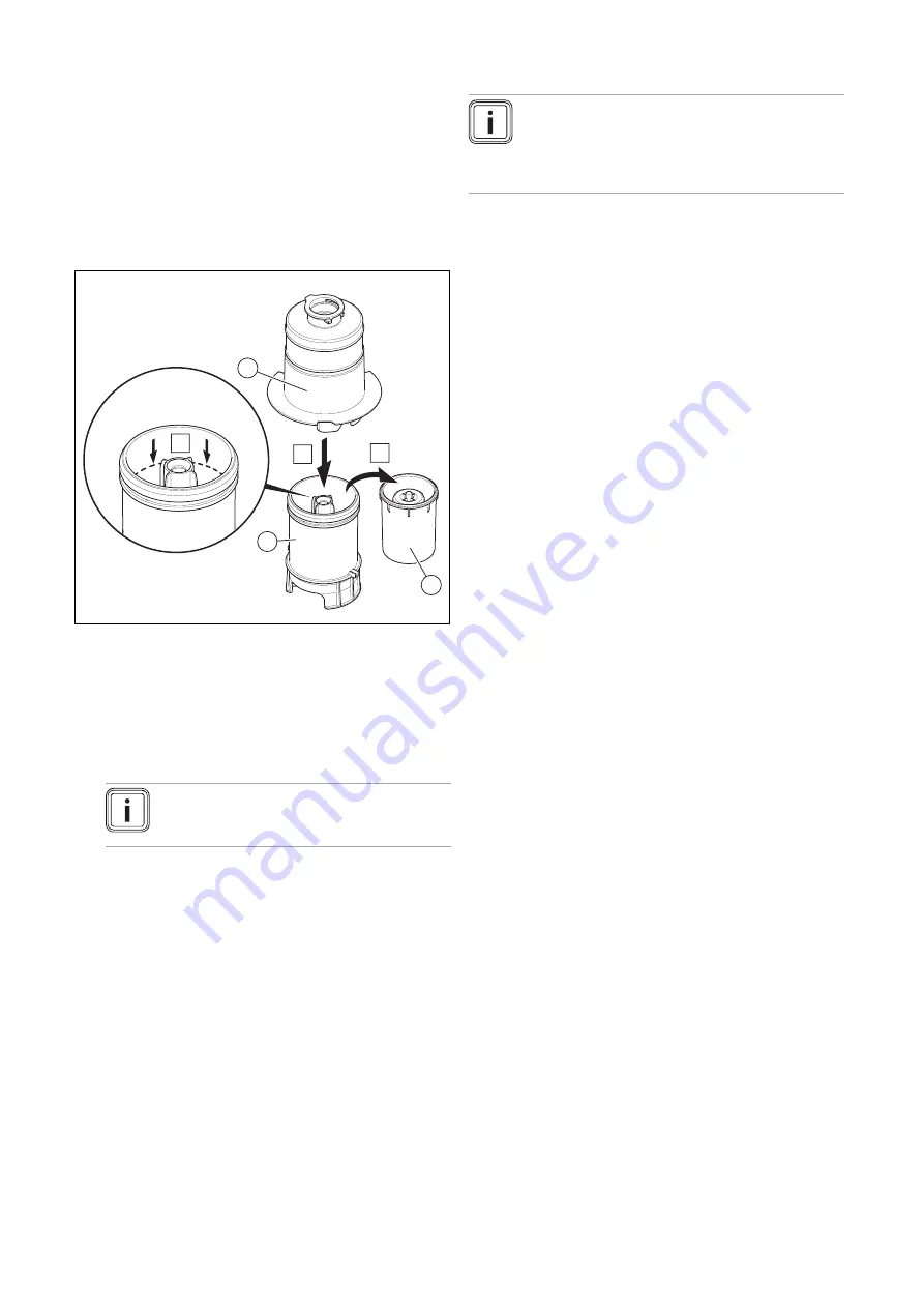
Filling the condensate trap
C
2
3
1
A
B
1.
Unclip the lower section of the condensate trap
(1)
from
the upper section of the condensate trap
(2)
.
2.
Remove the float
(3)
.
3.
Fill the lower section of the condensate trap with water
up to 10 mm below the upper edge of the condensate
discharge pipe.
4.
Re-insert the float
(3)
.
Note
Check whether the float is present in the
condensate trap.
5.
Clip the lower section of the condensate trap
(1)
into the
upper section of the condensate trap
(2)
.
9.4
Switching on the product
▶
Switch on the product via the main switch installed on-
site.
9.5
Flushing the heating installation for the first
time ("cold")
Note
The complete heating system must be flushed
at least twice: Once with cold water and once
with hot water in accordance with the following
instructions.
1.
Check whether all thermostatic radiator valves and both
service valves on the product are open.
2.
Connect a hose to the drain valve that is located at the
lowest position in the heating system.
3.
Open the radiator valves and the drain valves so that
the water can drain quickly. Start at the next point in the
installation and open the purging valves on the radiators
so that the contaminated water can completely drain.
4.
Close the drain cocks.
5.
Refill the heating system with water.
6.
Close the filling valve and the cold water tap.
9.6
Filling the heating installation
▶
Fill the heating installation with the maximum possible
volume flow.
9.7
Checking the gas setting
Only a qualified competent person is authorised to imple-
ment the settings on the gas valve assembly.
Each destroyed seal must be replaced.
The CO
₂
adjusting screw must be sealed.
Never modify the factory setting of the gas pressure regu-
lator of the gas valve assembly.
9.7.1
Checking the air/flue pipe/flue gas
recirculation
1.
Check the flue gas installation is intact in accordance
with the latest gas safe technical bulletin and informa-
tion supplied in the installation instructions.
2.
For extended flue gas installations check for flue gas
recirculation using the air analysis point.
3.
Use a flue gas analyser.
4.
If you discover unusual levels of CO or CO
2
in the sup-
ply air, search for the leak in the flue system or for signs
of flue gas recirculation.
5.
Eliminate the damage properly.
6.
Check again whether the supply air contains any unusal
levels of CO or CO
2
.
7.
If you cannot eliminate the damage, do not start up the
product.
9.7.2
Checking the gas flow rate
The gas flow rate has been set during production and does
not require adjustment. With the front casing fitted check the
gas flow rate of the boiler as follows:
▶
Start up the product with the check programme
P.01
.
▶
In addition, ensure that maximum heat can be dissipated
into the heating system by turning up the room thermo-
stat.
▶
Wait at least 5 minutes until the boiler has reached its
operating temperature.


