background image

General settings

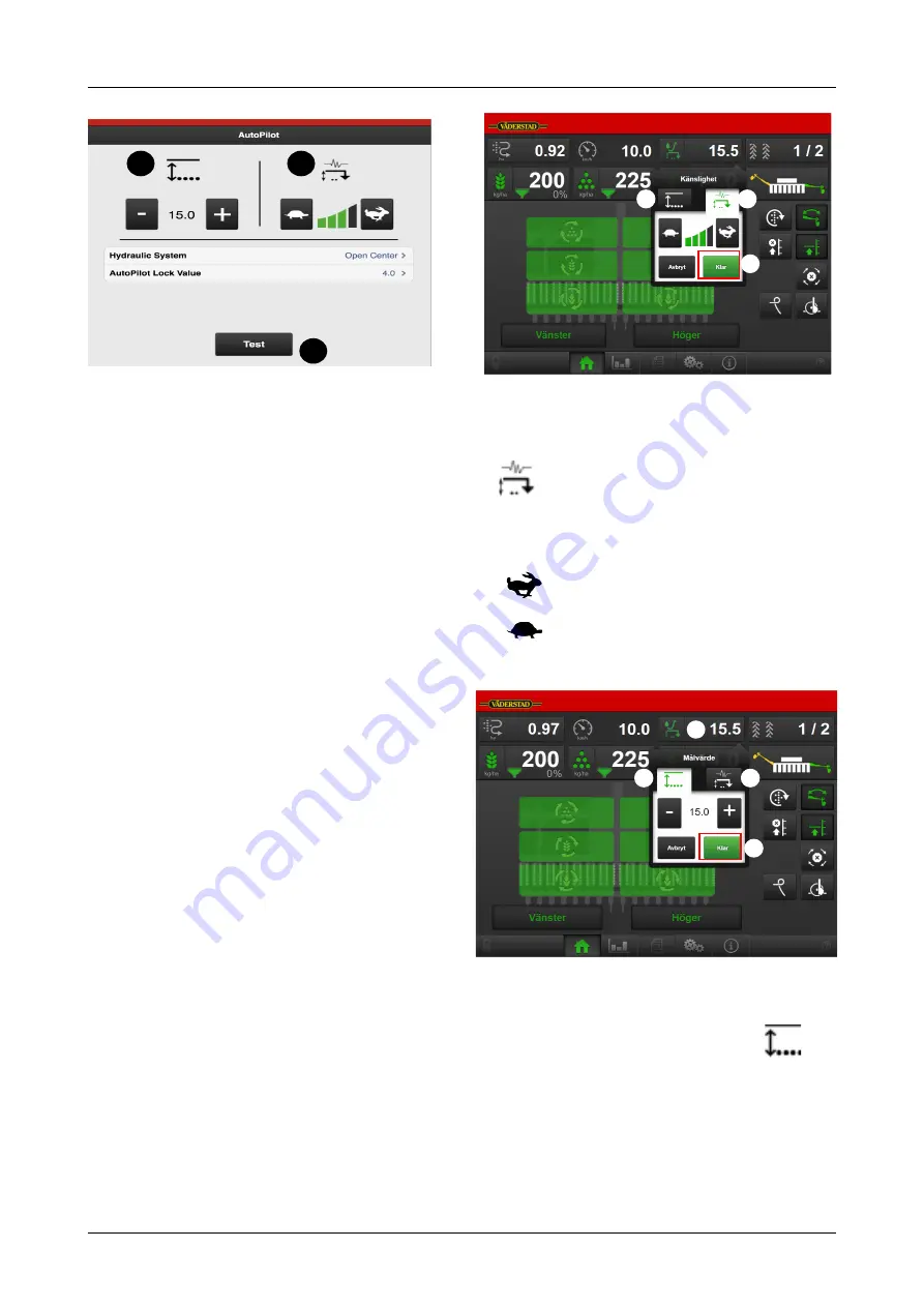
Figure 6.22

Setting the hydraulic system

A. First, select the hydraulic system type used by the

tractor.

If a tractor uses a constant oil flow system, which
means that the tractor’s hydraulic pump has a
fixed displacement, the AutoPilot hydraulic block
must have an Open Centre valve activated. This
valve allows oil to pass at low pressure through
the valve block even when no adjustment is made.
The valve can be opened by selecting Open
Centre.

Setting for older tractors that lift slowly. If your
tractor uses a constant pressure system, in which
the hydraulic system uses constant work pressure
regardless of the amount of oil consumed, the
Closed Centre option should be selected instead.

If your tractor has a load-sensing hydraulic
system, it is possible to select the option which is
best for the tractor: Open or Closed Centre. If
Open Centre is selected, the flow from the tractor
should be adjusted according to the “Setting the
oil flow rate” chapter in the machine’s instruction
manual.

If you are not sure which option to choose, please
contact your tractor supplier.

Setting the AutoPilot lock value

B. Setting the value for the AutoPilot lock. This function

prevents the AutoPilot system from lowering the
machine when it is raised from the furrow. The
AutoPilot lock locks the system for 4 seconds when
the Actual value deviates from the Set value by the
number selected here. The standard value is 4.
Normally, this does not need to be changed. However,
if the machine has a tendency to lower once it is
raised, a lesser value should be selected.

Figure 6.23

Selecting adjustment sensitivity

C. The desired adjustment sensitivity is entered using

(F) in the AutoPilot system menu on the home

screen (

“Figure 6.23 

) or, alternatively, in settings,

see

“Figure 6.22 

.

Faster adjustment

Slower adjustment

Press H (

“Figure 6.23 “

) to return to Drive mode

Figure 6.24

Setting the drilling depth

D. The desired drilling depth is entered using

(G)

in the AutoPilot system menu on the home screen
(

“Figure 6.24 

) or, alternatively, in settings, see

“Figure 6.22 

. This is possible when AutoPilot is

activated in general settings, see the menu on the
home screen (D,

“Figure 6.22 “

).

A

B

D

C

E

G

F

H

G

F

H

I

903099-en-gb; 19.01.2021

19

Содержание Rapid Series

Страница 1: ...903099 en gb 19 01 2021 07 Original instructions Instructions E services Rapid Version 1 6 3...

Страница 2: ...V derstad Holding AB V derstad Sweden 2018 903099 en gb 19 01 2021...

Страница 3: ...E Control 7 5 The home screen 8 5 1 Display for control and monitoring 8 5 2 Function buttons 9 5 3 Navigation buttons 10 5 4 Machine symbol 10 5 5 Tank level 11 6 General settings 12 6 1 Menu settin...

Страница 4: ......

Страница 5: ...not look exactly like the one you have depending on which optional extras have been fitted the model or whether any updates have been carried out Also consider downloading a new version of the instruc...

Страница 6: ...tion between the iPad and the machine s Gateway takes place wirelessly via a Wi Fi connection Gateway receives and processes all commands E Control has a large touchscreen with coloured menus which ma...

Страница 7: ...rtiliser amount hold down the B button and move UP DOWN using the E and H buttons C Alarms menu displayed as long as the button is held down D Statistics menu displayed as long as the button is held d...

Страница 8: ...connectors are aligned 3 Attach the connector using the latch clamp May look different for different tractors The terminal detects that a Gateway is connected and automatically imports the software 4...

Страница 9: ...t enabled you will be prompted to enable it on the screen 3 Press any button on the E Keeper The Bluetooth symbol will light up and the E Keeper will be ready to use The iPad must always be unpaired f...

Страница 10: ...d manually 4 1 1 If the network is not found automatically If connection to the network does not take place automatically the network connection must be enabled This might happen if for example you ha...

Страница 11: ...ation is the same for all V derstad machines equipped with E Control The system automatically detects the relevant machine type 4 3 Updating software in Gateway ISOBUS E Control Software is updated by...

Страница 12: ...the cab AutoCheck or automatic AutoPilot while driving D Tramlining See 6 4 Tramlining and 10 2 Setting tramlines Press the field in the work display to select the function Green symbol tramlining ena...

Страница 13: ...is selected see 8 Configuration The button opens the menu for hydraulic following harrow settings see 6 6 Hydraulic following harrow This selection should be made under the general settings if the hyd...

Страница 14: ...l setting is automatic advance of bout marker switching and tramlining program The button shows a white symbol This means that the bouts in the tramlining cycle are advanced and the bout markers are s...

Страница 15: ...ackground The unit is rotating against a white background The unit has stopped but will be re started when all the output criteria have been met against a grey background The unit is switched off agai...

Страница 16: ...entered in this menu Figure 6 2 A Manual start km h Customise the manual feed speed to the intended driving speed If the expected driving speed is e g 7 km h the speed 7 km h must be selected for manu...

Страница 17: ...e is pulling in one direction or if it is offset to one side Units are given in cm D Distance between the hitching point and ground contact point for example gauge wheels Units are given in cm 6 3 3 P...

Страница 18: ...in the tramlining cycle is programmed individually Figure 6 8 A detailed description of how to lay tramlining tracks and change track width as well as how row shut off works can be found in the machin...

Страница 19: ...ining programs are uppercase A Z lowercase a z and numbers 0 9 6 4 4 Open a saved tramline program Figure 6 12 Press B to display a list of saved tramline programs Open the saved program by selecting...

Страница 20: ...have not been acknowledged Select an alarm by using the UP DOWN arrows on the VT or press an alarm field on the iPad Information on the alarm is shown in the new window and the alarm can be acknowledg...

Страница 21: ...sed harrow 1 means lowest pressure and 30 means highest pressure Settings 1 Press the symbol for the function that is to be changed 2 Press to increase the pressure or to reduce the pressure The bar a...

Страница 22: ...ing machine should not exceed 10 cm in diameter To achieve the best results speed during drilling should be kept uniform If the tractor pulls the drill at low speed up a hill and at high speed down a...

Страница 23: ...al If you are not sure which option to choose please contact your tractor supplier Setting the AutoPilot lock value B Setting the value for the AutoPilot lock This function prevents the AutoPilot syst...

Страница 24: ...form a system test as follows 1 Lower the drill onto firm ground 2 Switch on the AutoPilot system and the oil supply from the tractor 3 Go into the menu for AutoPilot settings 4 Press the E button to...

Страница 25: ...rease decrease in the feed volume in the adjustment of sown amount If you select e g 5 the sown amount will change in increments of 5 every time the button is pressed in the operations menu F Output f...

Страница 26: ...he screen A Resets and starts the measurement B Finishes the calibration sequence C Shows the total number of radar pulses during calibration D Field to enter the distance driven when calibrating E Sh...

Страница 27: ...ocedure Torsion tests for seed fertiliser and BioDrill are to be conducted prior to starting the calibration of the oil flow Figure 7 6 Green numbers show the values from the torsion tests Red numbers...

Страница 28: ...ed Slip via ISO11783 connector 56 J Pre emergence bout marker OFF Pre emergence bout marker accessory Side bout marker Side bout marker as pre emergence bout marker When selected the side bout marker...

Страница 29: ...hat shows these results The reset action should then be confirmed in the pop up window that is displayed Section A Current drilling operation Season Total Section B area sown Area per hour average spe...

Страница 30: ...e first number shows which phase of the tramlining cycle you are in The second digit shows the number of tramlining cycles in the tramlining program see 6 4 Tramlining for setting the tramlining cycle...

Страница 31: ...tory information and detailed information on WorkStation inputs and outputs 11 1 Alarm history Pressing the Alarm History button in the top menu row will take you to a page containing alarm history in...

Страница 32: ...n on WorkStation inputs and outputs The green icon indicates which information is being displayed Figure 11 2 WorkStation 1 inputs A Inputs Shows a list of the current incoming signals to WorkStation...

Страница 33: ...Information Figure 11 3 WorkStation 1 outputs Figure 11 4 WorkStation 1 information 903099 en gb 19 01 2021 29...

Страница 34: ...Information Figure 11 5 Workstation 2 inputs Figure 11 6 Workstation 2 outputs 30 903099 en gb 19 01 2021...

Страница 35: ...Information Figure 11 7 WorkStation 2 information 903099 en gb 19 01 2021 31...

Страница 36: ...f the alarm appears although the seed meters Check the alert time that has been programmed Check the sensor The sensor is located in the tramline coupling Check connections and connectors to the traml...

Страница 37: ...valve max power Perform a new calibration Check the oil flow rate 101 Voltage low WorkStation 1 Inspect the connections and connectors of the intermediate cable The functions of the hydraulic system s...

Страница 38: ...e terminal If the iPad is not communicating with the dock check whether Bluetooth is enabled 281 Rotation guard fertiliser LH If the metering units do not move Check connections and connectors to the...

Страница 39: ...itting at the lower limit for permitted speed Check the oil flow rate Check the calibration Check the roller 770 Low speed fertiliser The hydraulic motor is sitting at the lower limit for permitted sp...

Страница 40: ...Motor speed input Ground 4 1 Fertilizer Motor speed input Digital In 4 2 4 3 Fertilizer Motor speed input 12 V 4 4 Fertilizer Motor speed input Ground 5 1 Rotation Guard BioDrill Right Digital In 5 2...

Страница 41: ...10 1 LowLift switch Analogue 10 2 Digital In 10 3 12 V 10 4 LowLift switch Ground 11 1 AutoCheck sensor Analogue 11 2 11 3 AutoCheck sensor 12 V 11 4 AutoCheck sensor Ground 12 1 12 2 Control main cyl...

Страница 42: ...ine BioDrill Left RDS Digital In 19 2 Tramline Fertilizer Left Tramline BioDrill Left RDS Digital Out 19 3 Tramline Fertilizer Left Rotation Guard Fertilizer Left RDC Tramline BioDrill Left RDS 12 V 1...

Страница 43: ...RDC 12 V 3 4 BioDrill Motor speed input RDC Ground 4 1 Seed depth guard sensor Autopilot Digital In 4 2 4 3 Seed depth guard sensor Autopilot 12 V 4 4 Seed depth guard sensor Autopilot Ground 12 1 12...

Страница 44: ...e PWM Out 20 3 12 V 20 4 Following harrow directional valve Ground 21 1 Digital In 21 2 Following harrow transport lock PWM Out 21 3 12 V 21 4 Following harrow transport lock Ground 22 1 Digital In 22...

Страница 45: ...eos are stored locally on your iPad To download to your iPad do the following 1 Connect to the Internet 2 Start the app Figure 14 1 3 Go to the How to page Figure 14 2 4 To download documents Press th...

Страница 46: ...d When the download has finished return to the How to home page to open the saved document Figure 14 7 Click on the line to open the document or video When a document is open not video you can use thr...

Страница 47: ...ously downloaded instructions or video the icon will be lit next to the instructions or video that can be replaced 14 3 Delete instructions or video If the memory is full an error message appears on s...

Страница 48: ...Where farming starts V derstad AB SE 590 21 V DERSTAD Sweden Phone 46 142 820 00 www vaderstad com...

Отзывы: