ZoomSHOT 20 QSR Camera System
ZoomSHOT 20 QSR System Document Number 342-0968 Rev A
Page 6 of 20
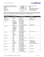
Rear Panel Connections with Callouts
Image: ZoomSHOT 20 HD Camera
1) RS-232 (Color Coded Blue):
The RS-232 RJ-45 accepts modified VISCA protocol for camera control.
2) EZ-POWER VIDEO Port (Color Coded Orange):
This RJ-45 connector is only used with the Quick-Connect
SR, Quick-Connect DVI-D/HDMI SR Interface, Quick-Connect USB and USB Mini Interfaces to supply power and
return HSDS (differential) video from the camera over Cat-5/5e/6 cable up to distance of 150’ (45.72m).
3) ZoomSHOT
20
DIP Switch Settings:
Settings for IR remote frequency, IR receiver on/off, image flip and
defaults can be configured on these switches. See the Switch Settings page for additional information. The dip
switch settings are as follows:
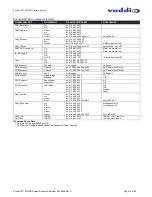
Table: ZoomSHOT 20 DIP Switch Settings
4) HD Video Select:
A rotary switch allows the user to choose the component HD output video resolution and format. After setting or
changing the resolution, reboot the camera to ensure proper operation. Simply set the rotary switch to an assigned
position to output video. The HD Video Select Rotary Switch Settings are as follows:
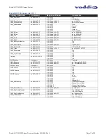
Table: ZoomSHOT 20 HD VIDEO Selections
Notes:
Set the rotary switch to an assigned position. If put on an unassigned position, then 720p/60 will be displayed.
DIP Switch
Function
1
Up = IR1, Down = IR2
2
Up = IR 1 or 2, Down = IR3
3
Up=IR ON, Down = IR OFF
4
Up = Normal Image, Down = Image Flip
5 Not
Used
6 Not
Used
All Down
Reset to Defaults - with power cycle
Rotary
Resolutions
Rotary
Resolutions
0
720p/59.94
8 1080p/50
1 1080i/59.94
9 --
2 1080p/59.94
A --
3 720p/60
B --
4 1080i/60
C --
5 1080p/60
D --
6 720p/50
E 1080p/30
7 1080i/50
F 1080p/25
①
②
③
④
Point the notch in
the switch stem to
assign the rotary
position


