VADDIO WallVIEW D80 Скачать руководство пользователя страница 6

WallVIEW D80 PTZ and WallVIEW D90 PTZ Manual 


© 2012 Vaddio - All Rights Reserved.  Document Number 342-0505 Rev A                                                                                    Page 6 of 12 


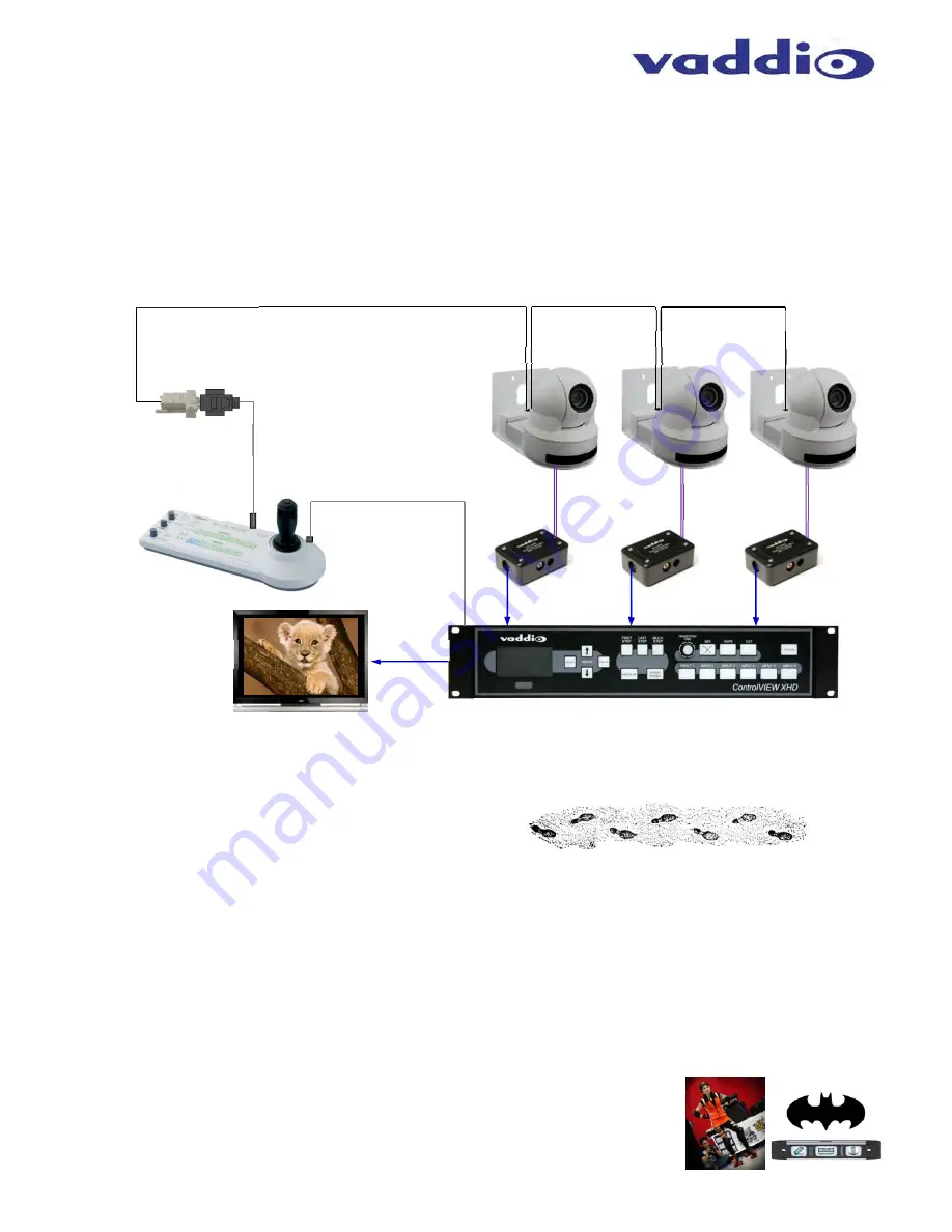
Diagram:  Daisy Chain Control Configurations 

The WallVIEW D80 PTZ and WallVIEW D90 PTZ are capable of supporting a daisy chain control configuration 
using a non-Vaddio controller (Sony Joystick or correctly written Crestron or AMX program).  Vaddio controllers 
support only direct connect, star wiring configurations for control because daisy chaining introduces another level 
of fault (Murphy’s Law) that makes for some tricky, time consuming system troubleshooting.  However, there is 
more than one way to configure systems and while Vaddio whole-heartedly recommends a one to one star 
configuration for control, the WallVIEW with the EZCamera Cabling Shoe also support daisy chain systems.  The 
Shoe has a RS-232 IN and a RS-232 OUT to support daisy chaining.  See diagram below: 


Note:  In the diagram above a video switcher/mixer is required because the control had to be separated from the 
switcher/mixer in order to accommodate the daisy chain control configuration.  


Step by Step Mounting and Install Instructions: 


Step 1:  Determine the Camera Mount Location: 

When locating the camera, consider viewing angles, lighting conditions, possible line of site obstructions and 
check for in-wall obstructions where the camera is to be mounted.  Select a mounting location to optimize the 
performance of the camera for your application.  
 
After determining the optimum location of the camera system, route the required Cat-5 cables from the camera 
location to the head-end.  Be sure to mark the cables and leave several inches of Cat-5 extending out from the 
wall for ease of connection. 

Step 2:  Determine the preferred Method of Wall Mounting 

1. 

Method 1:

 If the bracket is to be mounted on a 2-gang wall box, use the screws supplied with the wall box 

cover plate to attach the Thin Profile wall mount bracket.  
  

2. 

Method 2:

 If the bracket is to be mounted to the dry wall, then use the provided 

spiral wall anchors or other wall anchors of integrator’s choice.  Mount the wall 
mount to the anchors with the supplied #8 sheet metal screws.  The mounting 
holes are opposed 90° so leveling is easy…but use a level anyway, otherwise 
the result may be that funky Batman camera angle. 

20’ (6.1m) VISCA Cable 
(8-Pin mini din to DB-9M) 

Sony/Vaddio 
Joystick Package 
with adapter and 
cables 

EZCamera 

Control 

Adapter 

RS-232 on Cat-5 

RS-232 on Cat-5 

RS-232 on Cat-5 

Vaddio ControlVIEW XHD 6 x 1 Switcher/Mixer 

S-Video 

S-Video 

S-Video 

Power & 
Video Cat-5 

Power & 
Video Cat-5 

WallVIEW 80 PTZ Cameras (NTSC - White)

IN 

OUT 

IN 

OUT 

IN 

Tally Contacts 
to Switch Inputs 

Simulated 
Video Feed 

S-Video 

Содержание WallVIEW D80

Страница 1: ...TZ Camera Systems Wall Mounted Pan Tilt Zoom Camera Systems using Vaddio s EZCamera Cabling System Part Numbers WallVIEW D90 PTZ 999 2694 000 NTSC Black 999 2694 000W NTSC White 999 2694 001 PAL Black 999 2694 001W PAL White WallVIEW D80 PTZ 999 2684 000 NTSC Black 999 2684 000W NTSC White 999 2684 001 PAL Black 999 2684 001W PAL White Installation and User Guide ...

Страница 2: ...e Camera Mount Location 6 Step 2 Determine the preferred Method of Wall Mounting 6 Image PCBA inside the Shoe 7 Image Attaching the Shoe 7 Step 4 Attach the Camera and Shoe to the Wall Mount 7 Image Camera Shoe and Mount 7 Finishing the Install 8 Final Step 8 Documents and Information 8 Warranty Information 9 Appendix 1 10 Vaddio Power Video and Control Pin outs 10 Image The EZCamera Cable Shoe 10...

Страница 3: ...ust examine the product before operating To reduce the risk of electric shock do not immerse in water or other liquids and avoid extremely humid conditions Intended Use Before operating the device please read the entire manual thoroughly The system was designed built and tested for use indoors and with the provided power supply and cabling The use of a power supply other than the one provided or o...

Страница 4: ... Control Documentation Vaddio Manual and Sony Manual Four 4 WallVIEW D90 PTZ Systems 999 2694 000 NTSC Black One 1 Sony EVI D90N Black NTSC Camera One Peripheral Set with North American Power Cord Black Mount and Shoe 999 2694 000W NTSC White One 1 Sony EVI D90N W White NTSC Camera One Peripheral Set with North American Power Cord White Mount and Shoe 999 2694 001 PAL Black One 1 Sony EVI D90P Bla...

Страница 5: ... WallVIEW D90 PTZ can be mounted to standard 2 gang wall boxes All cameras are basically lightweight and the thin profile wall mount bracket can be adequately secured to the wall with the four 4 provided spiral wall anchors or your own choice of dry wall anchor Pick a mounting location to optimize the performance of the camera Pre wire all cabling as required mark and test the cables see wiring di...

Страница 6: ...ting conditions possible line of site obstructions and check for in wall obstructions where the camera is to be mounted Select a mounting location to optimize the performance of the camera for your application After determining the optimum location of the camera system route the required Cat 5 cables from the camera location to the head end Be sure to mark the cables and leave several inches of Ca...

Страница 7: ...ectors It should slide into place and make positive connection with a minimum of effort Step 4 Attach the Camera and Shoe to the Wall Mount Place the camera onto the camera mount and plug in the Cat 5 RJ 45 connectors Insert and loosely tighten the supplied 20 screw through the wall mount slot and secure the camera to the mount Gently push camera toward the front of the mount and align with front ...

Страница 8: ... position ready for control information from the provided Vaddio IR Remote Commander or RS 232 camera controller of the integrators choice Documents and Information For documents on video power and control pin outs please see the Vaddio website under Tech Center General Technical Notes WallVIEW Video Power and Control Pin Outs Technical or the Appendix at the back of this manual For RS 232 control...

Страница 9: ...ipping address and product serial numbers and describe the reason for repairs or returns as well as the date of purchase and proof of purchase Include your assigned RMA number in all correspondence with Vaddio Write your assigned RMA number on the outside of the box when returning the product All products returned for credit is subject to a restocking charge without exception Voided Warranty The w...

Страница 10: ...wer GND 1 Pin 3 Video GND 2 Pin 4 Y Luminace 3 Pin 5 Video GND 3 Pin 6 C Chrominance 2 Pin 7 Video GND 4 Pin 8 Composite Video CVBS 4 Table Diagram RS 232 IN Connection RJ 45 Pin outs Pin Function Pairs Pin 1 DTR Sony Daisy chain to DSR 1 Pin 2 DSR Sony Daisy chain from DTR 1 Pin 3 CTS Canon Daisy chain to RTS Not Used Pin 4 RTS Canon Daisy chain from CTS Not Used Pin 5 N A Not Used Pin 6 Digital ...

Страница 11: ...sed Pin 6 Digital GND Pin 7 TXD to RXD of control source 4 Pin 8 RXD from TXD of control source 4 Image Quick Connect Box Dimensions W x H x D 3 761 2 mm x 2 50 8mm x 1 25 4mm Table Diagram Power Video Connection RJ 45 on Quick Connect Box Pin Function Pairs Pin 1 Power 1 Pin 2 Power GND 1 Pin 3 Video GND 2 Pin 4 Y Luminace 3 Pin 5 Video GND 3 Pin 6 C Chrominance 2 Pin 7 Video GND 4 Pin 8 Composit...

Страница 12: ... 763 971 4464 www vaddio com 2012 Vaddio All Rights Reserved Reproduction in whole or in part without written permission is prohibited Specifications and pricing are subject to change without notice Vaddio WallVIEW Quick Connect EZCamera EZCable and PowerRite are trademarks of Vaddio All other trademarks are property of their respective owners Document 342 0505 Rev A ...

Отзывы: