background image

Camera Behavior Settings – RoboSHOT 12 USB

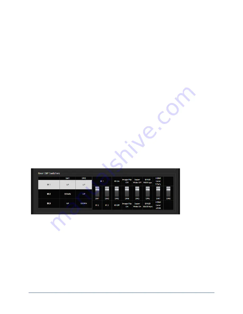
The RoboSHOT 12 USB camera uses DIP switches to set camera behaviors; the RoboSHOT 12E USB
and RoboSHOT 30E USB cameras set all camera behaviors in the web interface.

A label on the bottom of the camera provides a quick reference for setting the switches.

Set the switches appropriately before mounting the camera.

After the camera is installed, you can read the switches from the camera's web interface.

Note

When the camera is not inverted, DIP switches are in their default positions when they are up.

IR Frequency Selection:

If there are multiple cameras in the room, use

switches 1 and 2

to configure

each with a different IR frequency to allow the IR Remote Commander to control them independently. Then
use the Camera Select buttons at the top of the remote to select the camera you want to control.

n

SW1 and SW2 up: IR frequency 1

n

SW1 down, SW2 up: IR frequency 2

n

SW1 up, SW2 down: IR frequency 3

IR:

Leave

switch 3

in the default UP position if the IR remote will be used.

Image Flip:

If mounting the camera upside-down, set

switch 4

to the DOWN position: IMAGE FLIP ON.

This orients the video image correctly and sets the tilt motors to respond appropriately to tilt up and down
commands from the remote, web interface, and connected control devices.

Super Wide:

In normal mode, the camera has a 67.2º horizontal field of view (HFOV). For Super Wide

mode, set

switch 5

to the DOWN position for a 12X, 73º horizontal angle of view. 

Baud:

 Set

switch 6

to the baud rate of the device connected to the RS-232 port. The default is 9600 bps.

The 38400 baud setting is optional if the connected control device supports it.

HDMI Color:

Set the color space for the HDMI output to YCbCr (default; switch 7 UP) or sRGB.

Switch 8

is not currently used.

10

Installation Guide for RoboSHOT USB Enterprise-Class PTZ Conferencing Cameras

Содержание RoboSHOT 12E USB

Страница 1: ...Installation Guide for RoboSHOT USB Enterprise Class PTZ Conferencing Cameras Including RoboSHOT 12 USB RoboSHOT 12E USB and RoboSHOT 30E USB Document 411 0000 31 Rev C May 2019...

Страница 2: ...rial Communication Settings 11 RS 232 Connector Pin Out 11 Cabling Notes 12 Connecting the Camera 13 Basic Connections RoboSHOT 12 USB 13 Basic Connections RoboSHOT 12E USB or RoboSHOT 30E USB 14 Inst...

Страница 3: ...information is available in the Complete Manual for RoboSHOT USB Enterprise Class PTZ Conferencing Cameras Features n RoboSHOT 12 USB and RoboSHOT 12E USB 12x optical zoom perfect for huddle rooms and...

Страница 4: ...OT 12 USB North America 999 9920 000 silver and black RoboSHOT 12 USB Europe UK 999 9920 001 silver and black RoboSHOT 12 USB Australia New Zealand 999 9920 009 silver and black n RoboSHOT 12 USB Came...

Страница 5: ...SB 3 0 Type A to Type B cable 6 ft 1 8m n Quick Start Guide RoboSHOT 30E USB North America 999 99230 000 black 999 99230 000W white RoboSHOT 30E USB Europe UK 999 99230 001 black 999 99230 001W white...

Страница 6: ...e mode 10x in normal mode Recommended for small to medium sized conference rooms n RoboSHOT 12E USB 12x optical zoom recommended for small to medium sized conference rooms n RoboSHOT 30E USB 30x optic...

Страница 7: ...tions Provides uncompressed USB 3 0 stream n HDMI video select switch Select the appropriate HDMI video output resolution for the near end video display USB streaming resolution is auto negotiated IP...

Страница 8: ...n HDMI video select switch Select the appropriate HDMI video output resolution for the near end video display USB streaming resolution is auto negotiated IP streaming resolution is set in the adminis...

Страница 9: ...r recommended for use with it Always check the output voltage listed on the power supply label as power supplies for different products may look nearly identical Using the wrong power supply will void...

Страница 10: ...ded with the wall mount n If you mount it to a wall box use the cover plate screws supplied with the wall box If you install the camera wall mount to drywall use the wall anchors provided with the mou...

Страница 11: ...ite series cameras RoboSHOT 12 USB camera RoboSHOT 12E USB or RoboSHOT 30E USB camera For the newer Elite series cameras If the camera has been updated to version 3 1 0 firmware or later Position 0 se...

Страница 12: ...you want to control n SW1 and SW2 up IR frequency 1 n SW1 down SW2 up IR frequency 2 n SW1 up SW2 down IR frequency 3 IR Leave switch 3 in the default UP position if the IR remote will be used Image F...

Страница 13: ...8 Parity None Flow control None RS 232 Connector Pin Out Connector pin out n Pin 1 Not used n Pin 2 Not used n Pin 3 Not used n Pin 4 Not used n Pin 5 Not used n Pin 6 GND n Pin 7 RXD from TXD of con...

Страница 14: ...contact with cable connector Use Cat 5e or better cable We recommend using high quality connectors and a high quality crimping tool We recommend shielded cabling if the cables will be coiled run tight...

Страница 15: ...k administrator to determine how to configure the equipment Basic Connections RoboSHOT 12 USB Here is an example of how the RoboSHOT 12 USB camera might be set up in a medium size conference room In t...

Страница 16: ...oSHOT 30E USB Here is the same installation using an Elite series camera Again please note that the camera s output is USB 3 0 the EasyUSB Mixer Amp is USB 2 0 14 Installation Guide for RoboSHOT USB E...

Страница 17: ...amera to the desired settings 2 Route the cables through the opening in the mounting shelf and connect them to the camera Caution Use the power supply shipped with the camera Using a different power s...

Страница 18: ...main off when the camera is powered up The camera may be sending video even if the indicator light is off Next Steps The camera is now ready to configure and use This information is available in the C...

Страница 19: ...cause harmful interference to radio communications Operation of this equipment in a residential area is likely to cause harmful interference in which case the user will be required to correct the inte...

Страница 20: ...04 Corrigendum 2006 Electrical Fast Transients EN 61000 4 5 2006 Surge Immunity EN 61000 4 6 2009 Conducted Immunity EN 61000 4 8 2010 Power Frequency Magnetic Field EN 61000 4 11 2004 Voltage Dips In...

Страница 21: ...on If this equipment does cause harmful interference to radio or television reception which can be determined by turning the equipment off and on the user is encouraged to try to correct the interfere...

Страница 22: ...04 Corrigendum 2006 Electrical Fast Transients EN 61000 4 5 2006 Surge Immunity EN 61000 4 6 2009 Conducted Immunity EN 61000 4 8 2010 Power Frequency Magnetic Field EN 61000 4 11 2004 Voltage Dips In...

Страница 23: ...be contacted by email at support vaddio com or by phone at one of the phone numbers listed on support vaddio com Return Material Authorization RMA number Before returning a product for repair or repl...

Страница 24: ...t to restocking charges n The Dealer has up to 60 days from the date of purchase to return Vaddio product for credit for future purchases of Vaddio product only n The Dealer has 61 to 90 days from the...

Страница 25: ...ll be repaired under the non warranty terms if o The equipment has been damaged by negligence accident act of God mishandling used with the incorrect modified or extended power supply or has not been...

Страница 26: ...Customers requesting an estimate on repair charges must do so up front when they call in for an RMA The RMA team will call or email with the estimate after evaluating the unit and before proceeding wi...

Страница 27: ...US astronaut Terry Virts top left cosmonauts Alexander Samokutyaev and Anton Shkaplerov By NASA https www flickr com photos nasa2explore 16166230844 Public Domain https commons wikimedia org w index...

Страница 28: ...nt 8 inverted installation 8 IP address 13 preventing conflicts 13 static configuring before installation 13 IR frequency camera ID setting 10 L light status indicator 16 meaning of colors 16 location...

Страница 29: ...tch 8 IR 10 super wide mode 10 video resolution 10 T temperature operating and storage 16 third party control 11 V video resolution setting 9 visual parts identification 4 W wall mount 8 installing 8...

Страница 30: ...ecifications drawings manuals technical support information and more 2019 Legrand AV Inc Vaddio is a registered trademark of Legrand AV Inc All other brand names or marks are used for identification p...

Отзывы: