Adjustable Extension Mounting Bracket for CONCEAL
Adjustable Extension Mounting Bracket for CONCEAL Installation and User Guide 342-0395 Rev. A
Page 3 of 8
Mounting and Installation Instructions for the Adjustable Extension Wall Bracket for CONCEAL System:
Step 1: Determine the Camera Mount Location:
When locating the camera, consider viewing angles, lighting conditions, possible line of site obstructions and
check for in-wall obstructions where the camera is to be mounted. Select a mounting location to optimize the
performance of the camera for your application. After determining the optimum location of the camera system,
route the required Cat-5e cables from the camera location to the head-end.
Step 2: Determine the preferred Method of Wall Mounting:
For New Room Construction - Installation Option 1
(Allows the Adjustable Extension Bracket Arm to adjust
from 4” to 8” length):
For new construction, coordinate the installation of an electrical 2-Device Switch Box (Dimensions: 4” W x 4”H x
2-1/8” D) in the wall for the Adjustable Extension Wall Bracket for CONCEAL mounting location with the electrical
or general contractor.
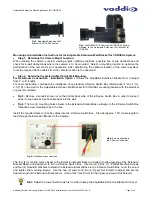
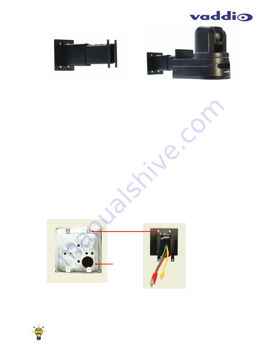
Fig 5:
Remove a conduit knock-out on the bottom back side of the 2-Device Switch Box in order to make it
easier to feed excess Cat-5e cable back into the wall.
Fig 6:
The four (4) mounting holes closest to the Extension Bracket Base will align to the 2-Device Switch Box
threaded screw mounting tabs in the box.
Install the required three (3) Cat-5e cables into the 2-Device Switch Box. Provide (approx. 1.5ft.) cable length to
feed through the Extension Bracket to the Camera.
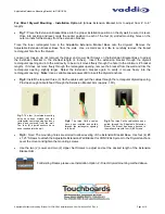
The four (4) mounting holes closest to the Extension Bracket Base are slotted (to allow leveling of the Extension
Bracket Base) and positioned to fit the 2-Device Switch Box. Use four (4) #6-32 X 1” Phillips Machine Screws
and four (4) Shoulder Washers to attach the Extension Bracket Base to the 2-Device Switch Box. Level the mount
and tighten the mounting screws. Use the two (2) Lower and two (2) Upper Set Screws to adjust and set the
desired length of the Extension Bracket Arm. (Use a 3/32” Hex Driver for the Upper and Lower Set Screws).
Hint:
Adjust the Lower Set Screws first in order to keep the Adjustable Extension Bracket Arm level.
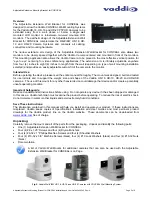
Fig 3:
Adjustable Extension Wall
Bracket for CONCEAL System
Fig 4:
WallVIEW HD-19 Camera with CONCEAL System
mounted to the Adjustable Extension Wall Bracket for
CONCEAL
Fig.5:
Conduit knock-out removed
Fig.6:
Screws attached to
the 2-Device Switch Box


