PC
BOARDS
Service Manual M4 - M10
22.10.2001
Page
91
8.
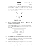
Before to assemble a new Power board into the drive do all the
required settings to the board according to instructions in section 9.2.6.
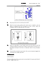
Assemble the board into drive in reversed order of the procedure
above.
9.
Check all the connections and order of the wire harnesses plugged into
connectors.
9.2.8 Spare parts
Power boards and resistor kits.
Detailed information for the spare parts is available from spare parts lists in
section “SPARE PART LIST”.
9.3 Control board
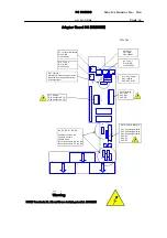
9.3.1 Description
Control board is the part of the control circuitry, where intelligence such as
features of the motor control is loaded in and tasks needed to control motor
properly are processed.
On the board all firmware, as well as parameter values are stored into
memory chips.
The Control board provides isolation from main circuit to process interface.
The plug-in terminals for the process control are placed on the board.
Multi layer technique is used in design of artwork of the board.
The SMD components are the mostly used on the board for high density
design.
Digital inputs
-
Configured in two separate groups, which are galvanically isolated
from each other.
-
Voltage level 0 - 10V corresponds a logical status “0” and respectively
status “1” is represented by voltages above 10V.
-
Maximum voltage is 30V and should not be exceeded!
-
Input impedance 4kohm.
-
Reaction time less than 12ms.
-
Open input represents status “0” at input.
-
Digital inputs can be configured to operate in positive or in negative
logic.
Two analog inputs, one voltage and one current input
-
Operation range to voltage input is -10V...+10V.
-
Input impedance 200kohm.
Содержание CX
Страница 1: ......
Страница 33: ...TROUBLESHOOTING Service Manual M4 M10 11 07 2002 Page 33 ...
Страница 34: ...TROUBLESHOOTING Service Manual M4 M10 11 07 2002 Page 34 ...
Страница 148: ...SPARE PART LISTS Service Manual M4 M10 Page 148 ...


