79
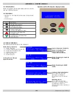
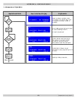
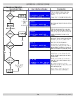
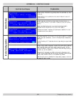
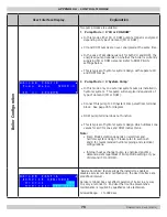
User Interface Display
Explanation
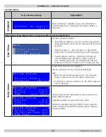
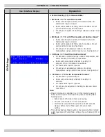
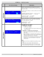
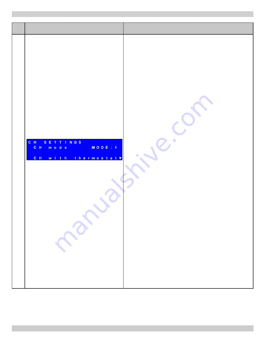
CH Settings
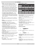
4. Central Heating (CH) modes available:
• CH Mode = 0 ‘CH with Thermostat’
• Boiler will attempt to satisfy CH demand while CH
thermostat input is closed.
•
Boiler will modulate its firing rate to maintain CH set
point and match system heat load.
• CH set point adjusted in ‘Settings’ submenu under ‘User
Menu’
• CH Mode = 1 ‘CH with Thermostat and Outdoor Reset’
• Boiler will attempt to satisfy CH demand when CH
thermostat input is closed.
•
Boiler will modulate its firing rate to maintain CH set
point and match system heat load.
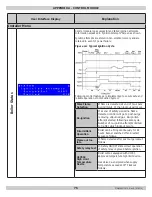
• CH set point calculated as function of outdoor
temperature using outdoor reset curve. See figure A-2
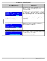
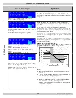
• CH Mode = 2 ‘CH with Full Outdoor Reset’
• CH demand is determined by outdoor temperature and
Warm Weather Shutdown temperature.
• Boiler will permanently attempt to satisfy CH
demand, when CH demand is available.
• CH thermostat input is ignored.
• CH set point calculated as function of outdoor
temperature using outdoor reset curve. See figure A-2
• CH Mode = 3 ‘CH with Permanent Demand’
• CH demand is permanently on.
• Boiler will permanently attempt to satisfy CH
demand.
• CH thermostat input is ignored.
• CH set point is adjusted in ‘Settings’ submenu under
‘User Menu’
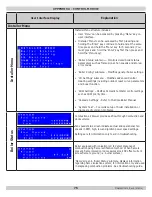
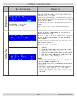
Note:
• Once CH demand is satisfied (i.e. CH thermostat opens or
boiler determines its minimum firing rate exceeds system
heating load):
• Burner shuts off, boiler enters post purge.
• CH pump continues to run for 30 seconds.
• Control will wait until Anti-cycle time of 180 seconds
elapses before boiler fires again. Prevents short-
cycling.
• The internal heat exchanger pump is energized anytime demand
exists regardless of Pump Mode setting or type of demand (CH or
DHW).
APPENDIX A - CONTROL MODULE
P/N# 240010615, Rev. E [07/2015]
Содержание SSV-050
Страница 50: ...50 13 TROUBLE SHOOTING P N 240010615 Rev E 07 2015 ...
Страница 52: ...52 13 TROUBLE SHOOTING P N 240010615 Rev E 07 2015 ...
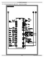
Страница 64: ...64 14 1 Connection Diagram 050 075 100 MBH 14 WIRING DIAGRAM P N 240010615 Rev E 07 2015 ...
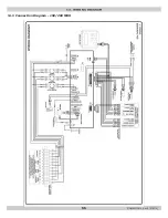
Страница 65: ...65 14 2 Schematic Diagram of Ladder Form 050 075 100 MBH 14 WIRING DIAGRAM P N 240010615 Rev E 07 2015 ...
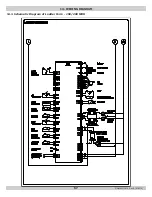
Страница 66: ...66 14 3 Connection Diagram 150 200 MBH 14 WIRING DIAGRAM P N 240010615 Rev E 07 2015 ...
Страница 67: ...67 14 4 Schematic Diagram of Ladder Form 150 200 MBH 14 WIRING DIAGRAM P N 240010615 Rev E 07 2015 ...


