


11
12
3.3
Web Page Configuration Guide
3.3.1
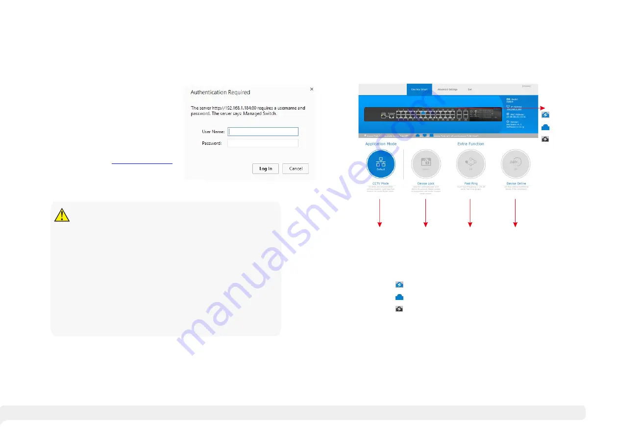
Start and Login
This product web default IP address:
1 9 2 . 1 6 8 . 1 . 2 0 0 , s u b n e t m a s k :
2 5 5 . 2 5 5 . 2 5 5 . 0 , a d m i n i s t r a t o r
account
:
admin, password
:
admin.
A f t e r i n s t a l l i n g t h e e q u i p m e n t
correctly and setting up the computer,
open the browser, input the switch
d e f a u l t a d d r e s s i n t h e b r o w s e r
address bar:
,
http://192.168.1.200
then press the Enter key, the user
login page will show in front of you as
follows:
The browser version recommend
:
IE7 and later, Firefox browser, Chrome, 360
browser (IE7 and later).
Please follow the steps to check if the switch is installed correctly:
(1) Whether the physical connection of the equipment is correct?
Use network cable to connect the product’s Ethernet port(except the
console port) with managed computer network card, and ensure
the link
LED of the port is on.
(2) Whether the computer TCP/IP agreement setting is correct?
Your computer's IP address must be 192.168.1.x (x range is 1 254 and x
~
can not be 200, otherwise it will conflict with the product IP address
192.168.1.200 ), subnet mask: 255.255.255.0.
(3) Whether
the computer's port VLAN ID is 1?
By default, the management VLAN is VLAN 1,
same as each port of switch.
Caution
After inputting the correct password, click <Login in>, the browser will display
the product Web management page.
3.3.2
One-key smart introduction
Ports indicator
PoE + link
Link(no PoE)
PoE(no link)
CCTV
LOCK
RING
ONLINE
One-key smart web management page diagram
(1)Ports indicator:
the switch diagramm can show the ports link and PoE-output status.
PoE + link
Link(no PoE)
PoE(no link)


