background image


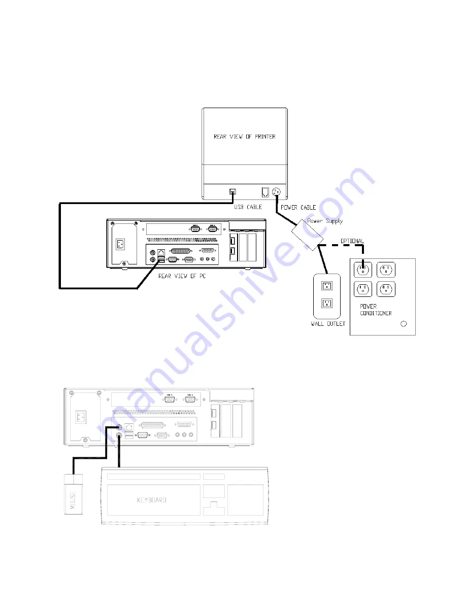
4.  Connect the printer USB cable from the printer to a USB port on the rear of the PC. 

5.  Connect the power cable from the printer power supply to the connector on the printer.  Connect 

the AC cable to the printer power supply and then to a wall outlet or the optional Power 
Conditioner. 


Figure 3: 

Rear View of components 


6.  Connect the mouse and keyboard cables to the PC.  The mouse port on the PC is green and the 

keyboard port is purple. 

Figure 4: 

Rear View of PC and Top views of keyboard and mouse 

© 2008 UTC RETAIL. All rights reserved. 

  11692012 Rev D 


Page 6 of 12 


Содержание 2200 Series

Страница 1: ...n Guide Thank you for selecting UTC RETAIL s innovative 2200 Series Point of Sale bundle solution This guide is designed to help you efficiently assemble the 2200 Series POS Bundle System 2008 UTC RETAIL All rights reserved 11692012 Rev D Page 1 of 12 ...

Страница 2: ...onable protection against harmful interference when the equipment is operated in a commercial environment This equipment generates uses and can radiate radio frequency energy and if not installed and used in accordance with the instruction manual may cause harmful interference to radio communications Operation of this equipment in a residential area is likely to cause harmful interference in which...

Страница 3: ... 11692012 Rev D Page 3 of 12 Table of Contents 2200 Series POS Bundle System Installation Guide 2 Product Information 4 Un boxing the System 5 Installation 5 Powering On Your 2200 Series POS Bundle System 11 Troubleshooting Procedures 12 ...

Страница 4: ...isplay Cash drawer Barcode scanner POS receipt printer Keyboard Mouse Note The following optional items may or may not be present depending on the configuration purchased and may be shipped in a separate box Magnetic Stripe Reader MSR Payment Terminal Pin Pad device power supply cables Payment Terminal Signature Capture device power supply cables Customer Display Inventory Scanner AC Power Conditi...

Страница 5: ...cable package labeled APG cash drawer 320 Multipro cable kit Connect the end with the larger modular plug into the jack on the base of the cash drawer Figure 1 Bottom View of Drawer 2 Lay down the cash drawer and place the cable to the side 3 Connect the other end of the cash drawer cable to the POS printer drawer port labeled DK Figure 2 Bottom View of Drawer 2008 UTC RETAIL All rights reserved 1...

Страница 6: ...ect the AC cable to the printer power supply and then to a wall outlet or the optional Power Conditioner Figure 3 Rear View of components 6 Connect the mouse and keyboard cables to the PC The mouse port on the PC is green and the keyboard port is purple Figure 4 Rear View of PC and Top views of keyboard and mouse 2008 UTC RETAIL All rights reserved 11692012 Rev D Page 6 of 12 ...

Страница 7: ... the LCD Display Connect the AC cable to the LCD power supply and then to a wall outlet or the optional Power Conditioner Figure 5 Bottom View of LCD and Rear View of PC 9 Connect the USB connector end of the Barcode Scanner cable to a USB port on the back of the PC Connect the other end into the jack on the barcode scanner handle Figure 6 Rear View of PC 2008 UTC RETAIL All rights reserved 116920...

Страница 8: ...onnect the optional Payment Terminal Pin Pad or Signature Capture device to a Serial Port on the back of the PC For instructions on the Signature Capture device cable connections refer to the install guide included with the terminal Plug the AC power adapter into a wall outlet or the optional Power Conditioner Figure 8 Rear View of PC and Top View of Pin Pad device 2008 UTC RETAIL All rights reser...

Страница 9: ...gure 9 Rear View of PC 13 Connect the optional Inventory Scanner to a serial port on the back of the PC Then plug the AC power adapter into a wall outlet or the optional Power Conditioner Figure 10 Rear View of PC and Top View of Inventory Scanner 2008 UTC RETAIL All rights reserved 11692012 Rev D Page 9 of 12 ...

Страница 10: ...n the back of the PC Figure 11 Rear View of PC 15 Plug the PC power cord into the receptacle on the rear of the PC and then into the wall outlet or optional Power Conditioner Figure 12 Rear View of PC 2008 UTC RETAIL All rights reserved 11692012 Rev D Page 10 of 12 ...

Страница 11: ...n the front left hand side of the PC 3 To activate the printer turn on the printer rocker switch located on the front of the printer 4 To activate the monitor depress the on off switch located on the lower right hand side of the monitor bezel You have completed the installation of UTC RETAIL s 2200 Series Bundled Point of Sale System If you experience problems with any of the components of the 220...

Страница 12: ... to the printer Make sure that the printer power switch is ON The printer has power but the system does not boot to Windows Push the ATX power button in the front of the logic unit located on the front left hand side of the PC A keyboard error message displays when you boot the 2200 Series POS unit Check to see if the keyboard cable is properly connected to the keyboard Make sure that the keyboard...

Отзывы: