UTC Fire and Security EDWARDS WG4WN-SVMHC Скачать руководство пользователя страница 3

P/N 3101853 • REV 2.0 • ISS 21MAR11 


3 / 4 

Maintenance 

This unit is not serviceable or repairable. Should the unit fail to 
operate, contact the supplier for replacement. 

Perform a visual inspection and an operational test twice a 
year or as directed by the local authority having jurisdiction. 

Caution: 

Do not change the factory-applied finish. 


Specifications 

 
Operating voltage 
 Speaker 
 Default 
 Strobe 

 
25 VRMS or 70 VRMS, switch selectable 
70 VRMS 
24 VDC, 24 VFWR nominal 

Supervisory voltage 

30 V max. 

Sound level output 

See Table 4 

Speaker response 

400 to 4,000 Hz 

Strobe operating current  See Table 8  

Light output 

Table 5, Table 6, and Figure 6 

Wire size 

12 to 18 AWG (0.75 to 2.50 mm²) 

Compatible electrical 
box 
 Wet 
 Dry 


Model 449 
4 in. square by 1-1/2 in. deep box 

Operating environment 
 Temperature 
 Relative 

humidity 

Wet 

31 to 151°F (

35 to 66°C) 

0 to 95% noncondensing 

Table 3: Compatible synchronization sources models 

Name Number 

Auto-Sync Output 
Module 

SIGA-CC1S 
GSA-MCC1S 

GSA-CC1S
SIGA-CC2A 

SIGA-MCC1S
SIGA-MCC2A

Genesis Signal 
Master Remote 
Mount 

ADTG1M-RM 
MG1M-RM 

G1M-RM EG1M-RM 

Table 4: Sound level output (dBA) 

Wattage 

Setting 

25 V 

70 V 

2 W 

90.0 

89.7 

1 W 

87.1 

86.9 

1/2 W 

84.0 

83.9 

1/4 W 

80.8 

80.8 

dBA = Decibels, A-weighted. 

UL 1480: Sound level output at 10 ft. (3.05 m) measured in a 
reverberant room using 400 to 4,000 Hz band-limited pink noise. 

Table 5: Indoor strobe output (cd) 

Lens 

Standard 

D C B A 

Clear UL 

1971 102 123 147 161 

Amber 

UL 

1638 84  101 125 130 


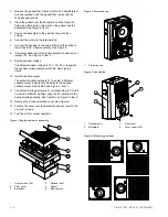
Figure 5: Wiring, JP1, and switch locations 

SPKR +

SPKR +

STROBE -

STROBE -

SPKR -

SPKR -

2

3

1

4

Detail A

5


1. Wire 

slot. 

2. 

S1 wattage-setting switch (see Table 4). 

3. 

S2 candela-setting switch (see Table 5). 

Note: Polarity shown in alarm condition 


4. 

JP1 strobe temporal mode selection jumper. 

5. 

S3 speaker voltage-setting switch. UP position is 70 V (default); 
DOWN position is 25 V. 

Содержание EDWARDS WG4WN-SVMHC

Страница 1: ...aker strobe 25 70 V white without marking 102 123 147 161 cd clear lens 1 Only indoor strobes with a clear lens comply with the latest requirements of UL 1971 Signaling Devices for the Hearing Impaired Table 2 Accessories Number Description WG4WTS 1 Outdoor rated surface skirt white for Genesis WG4 speaker or speaker strobe WG4RTS 1 Outdoor rated surface skirt red for Genesis WG4 speaker or speake...

Страница 2: ...osition the speaker voltage setting switch S3 See Figure 5 item 4 10 Set the candela output The default candela setting is D To select a different candela output align the S2 indicator to the desired candela output See Table 5 and Figure 5 item 1 11 The default wattage setting is Z corresponding to 1 4 watt To select a different wattage align the S1 indicator to the desired wattage setting See Tab...

Страница 3: ...o 151 F 35 to 66 C 0 to 95 noncondensing Table 3 Compatible synchronization sources models Name Number Auto Sync Output Module SIGA CC1S GSA MCC1S GSA CC1S SIGA CC2A SIGA MCC1S SIGA MCC2A Genesis Signal Master Remote Mount ADTG1M RM MG1M RM G1M RM EG1M RM Table 4 Sound level output dBA Wattage Setting 25 V 70 V 2 W T 90 0 89 7 1 W X 87 1 86 9 1 2 W Y 84 0 83 9 1 4 W Z 80 8 80 8 dBA Decibels A weig...

Страница 4: ...UTC Fire Security Americas Corporation Inc 8985 Town Center Parkway Bradenton FL 34202 USA Year of manufacture The first two digits of the DATE MFG number located on the product identification label are the year of manufacture UL rating Regulated 24 DC Regulated 24 FWR Synchronization Meets UL 1971 requirements 1 North American standards Meets UL 1971 1 UL1638 UL1480 Follow NFPA 72 FCC compliance ...

Отзывы: