


P/N 1061018 • REV E • ISS 14JUL11
5 / 8
Figures
Figure 1: 250-CO
Figure 2: Detector locations
Recommended CO detector location
Figure 3: 250-CO components
(1) Alarm
relay
(2) Terminals
“
−
” and “+” are for power; terminals “NO” (normally
open) and “C” (common) are the common trouble relay shown in
the normal state for this detector
(3) Sensor
(4) Sounder
Figure 4: Single device, single zone configuration
(1) Power (see Specifications)
(2) Alarm initiating device circuit (IDC) (normally open)
(3) End-of-line device (provided by the life safety system)
Note: Relay is shown in the normal state for this detector.
Figure 5: Multiple devices, single zone configuration
(1) Power (see Specifications)
(2) Alarm IDC (normally open)
(3) End-of-line device (supplied by life safety system)
Note: Relay is shown in the normal state for this detector.
Figure 6: Multiple devices, separate alarm, trouble zone
configuration
(1) Power (see Specifications)
(2) Alarm IDC (normally open)
(3) Supervisory IDC (normally open)
(4) End-of-line device (provided by the life safety system)
Note: Relay is shown in the normal state for this detector.
Figure 7: 250-CO features
(1) Test/hush
button
(2) Sensor
port
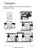
Installation
WARNING:
Potential loss of life. Failure to properly install,
test, and maintain a CO detector may cause it to fail. Connect
the CO detector only to a zone that is dedicated exclusively to
CO detection and that is monitored 24 hours a day. Do not
connect to an initiating circuit with fire or security devices.
The 250-CO SafeAir Carbon Monoxide Detector is a four-wire
device designed to use a Class 2 output from a control panel
listed to the ANSI/UL 985 or 864 standards or auxiliary power
supply.
All wiring must conform to the NFPA 70
National Electric Code
,
ANSI/UL 2075
Standard for Gas and Vapor Detectors and
Sensors
, NFPA 720
Standard for the Installation of Carbon
Monoxide
(CO) Detection and Warning Equipment
, applicable
codes, and the local AHJ.
The 250-CO SafeAir Carbon Monoxide Detector is intended for
indoor-dwelling unit applications in both residential and
commercial occupancies, including single/multiple family
residential occupancies, hotel rooms, dorm rooms, and other
areas approved by the authority having jurisdiction (AHJ).
The 250-CO detector can connect to either UL 985 (Household
Fire Warning) or UL 864 (Commercial Fire) control panels. It is
not intended for use in industrial applications such as gasoline
refineries or parking garages, which require different listings.
The 250-COPLT adapter plate
The 250-CO detector has an optional adapter mounting plate.
Use the 250-COPLT adapter plate when replacing a 240-COe
with a 250-CO to cover the footprint of the 240-COe. To
purchase the plate order P/N 250-COPLT-5PKG.
To install the detector without using the adapter plate:
1. Run the 250-CO detector wiring to the detector location.
2. Carefully remove the cover from the detector using a
small, flat screwdriver blade in the slot on the left side of
the detector cover.
3. The mounting hole pattern is for single-gang spacing. Use
the base for a template to mark the two screw hole
locations on the mounting surface or mount on a single-
gang box (not provided). The unit can be mounted
vertically or horizontally.
4. Install two screws on the marks. If necessary, use wall
anchors.
5. Line up the base with the screws, pull the wires through
the square holes, and then slide the base over the screws.
For surface wiring, pull the wires through the wiring
channel at the bottom of the base.
6. Strip 3/8 in. of insulation from each wire.
7. Determine the correct wiring, and then insert the wires
under the appropriate screw terminals. See "Wiring" and
Figure 4 to Figure 6.
8. Tighten both screws to secure the base to the wall.
9. Replace the detector cover.
10. Apply power. The LED should flash green for
approximately four seconds, and then pulse green.
11. Test in accordance with “Testing” on page 6.
To install the detector using the adapter plate:
1. Run the 250-CO detector wiring to the detector location.
2. Using the 250-COPLT wall plate for a template, trace the
perimeter of the two square holes on the mounting
surface. Also mark the two screw locations.
3. Cut out the two square holes.
4. Install two screws on the marks. If necessary, use wall
anchors.
5. Mount the wall plate but do not fully tighten the screws.
6. Carefully remove the cover from the detector using a
small, flat screwdriver blade in the slot on the left side of
the detector cover.
7. Pull the wires through the square holes on both the wall
plate and the 250-CO base. Then slide the detector base
over the screws.
firealarmresources.com


