background image

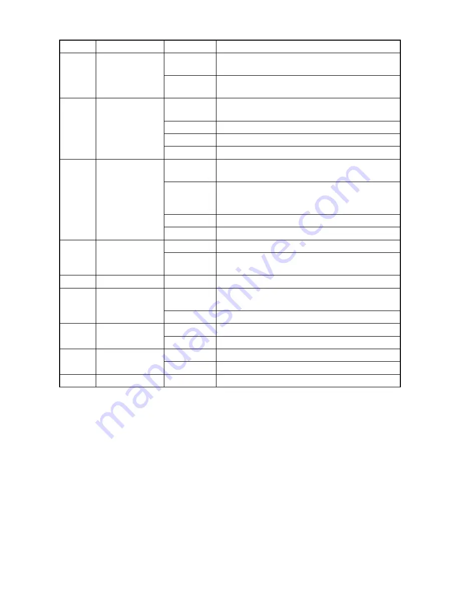
2

December 2012

2-4-9

Setting-range change of X9: 0 and 1 are changed into 0 

and 2.

2-4-11 to 14

Addition of the connector of  YC9 (110V only) :2-4-11, 13

Correction of header (the model number) : 2-4-11 to 14

3

15 February 2013

Contents

Correction of page

2-4 Appendix

1-4-23

Notes addition (F code)

1-4-11 to 20

F code addition 

Address

Changed the address of souse africa

4

12 September 2013 Contents

2-4-11

2-4-1  (4) Maintenance command addition

1-3-6

1-3-22, 23

Added the comments: 

(25) of Service status page and (9)Count/(11)-(h) of 

Event log 

2-4-4

Change of Setting value and Factory setting for N5

2-4-6

Correction of Factory setting for S7

5

26 December 2013

1-1-2

Added the comments:  First print 

2-2-7, 2-2-8

Correction: change of the No.2 and No.3 and change of 

the parts name

6

31 March 2014

2-4-13 to 20

Correction: The conditions of USBLOG acquisition

7

18 August 2014

1-3-4

1-3-7 to 9

Correction: Description of Service Status Page

1-3-7

Correction: temperature 

 humidity in (48) and (49)

8

8 September 2014

1-3-4

Correction: Description of Service Status Page

1-6-1, 1-6-2

Correction: Procedure

9

6 November 2014

1-1-1

Change: Hagaki, Oufuku Hagaki

1-3-7 to 9

Added: Description of the counter value

A

23 February 2015

1-3-8

Change: 5 to 100(%)

Revision

Date

 pages

Revised contents

Содержание P-4030D

Страница 1: ...Service Manual Monochrome Printer P 4030D P 4030DN P 4530DN P 5030DN P 6030DN Rev A 0 Date 25 02 2015 2LVSM06A ...

Страница 2: ...Service Manual Monochrome Printer P 4030D P 4030DN P 4530DN P 5030DN P 6030DN Rev A 0 Date 25 02 2015 2LVSM06A ...

Страница 3: ...ECT METTRE AU REBUT LES BATTERIES UTILISEES SELON LES INSTRUCTIONS DONNEES Il peut être illégal de jeter les batteries dans des eaux d égout municipales Vérifiez avec les fonctionnaires municipaux de votre région pour les détails concernant des déchets solides et une mise au rebut appropriée Notation of products in the manual For the purpose of this service manual products are identified by print ...

Страница 4: ...added 1 3 10 Addition of Description OP Network Status was added 1 3 11 Addition of Description Test Page was added 1 4 19 Addition of Description The check of TRA31was added 1 4 24 30 Addition of Description 15 Carrier leaking occurs was added 1 5 9 10 Change of Procedures Procedures of 3 Detaching and refitting the MP paper feed pulley was changed 1 5 31 Correction of Figure 1 5 52 Developer fan...

Страница 5: ...2 4 4 Change of Setting value and Factory setting for N5 2 4 6 Correction of Factory setting for S7 5 26 December 2013 1 1 2 Added the comments First print 2 2 7 2 2 8 Correction change of the No 2 and No 3 and change of the parts name 6 31 March 2014 2 4 13 to 20 Correction The conditions of USBLOG acquisition 7 18 August 2014 1 3 4 1 3 7 to 9 Correction Description of Service Status Page 1 3 7 C...

Страница 6: ...rsonnel to ensure the safety of their customers their machines as well as themselves during maintenance activities Service personnel are advised to read this booklet carefully to familiarize themselves with the warnings and precautions described here before engaging in maintenance activities ...

Страница 7: ... this symbol CAUTION Bodily injury or damage to property may result from insufficient attention to or incorrect com pliance with warning messages using this symbol Symbols The triangle symbol indicates a warning including danger and caution The specific point of attention is shown inside the symbol General warning Warning of risk of electric shock Warning of high temperature indicates a prohibited...

Страница 8: ...d or dusty place This may cause fire or electric shock Do not install the copier near a radiator heater other heat source or near flammable material This may cause fire Allow sufficient space around the copier to allow the ventilation grills to keep the machine as cool as possible Insufficient ventilation may cause heat buildup and poor copying performance Always handle the machine by the correct ...

Страница 9: ... carefully Always check that the copier is correctly connected to an outlet with a ground connection Check that the power cable covering is free of damage Check that the power plug is dust free If it is dirty clean it to remove the risk of fire or electric shock Never attempt to disassemble the optical unit in machines using lasers Leaking laser light may damage eyesight Handle the charger section...

Страница 10: ... caution labels that should be present on the machine according to the instruction handbook are clean and not peeling Replace with new ones if necessary Handle greases and solvents with care by following the instructions below Use only a small amount of solvent at a time being careful not to spill Wipe spills off completely Ventilate the room well while using grease or solvents Allow applied solve...

Страница 11: ...This page is intentionally left blank ...

Страница 12: ...etection 1 4 1 1 Paper misfeed indication 1 4 1 2 Paper misfeed detection condition 1 4 1 2 1 PF 320 500 sheets Paper feeder 1 4 1 2 2 PF 315 Bulk Paper Feeder 1 4 2 1 4 2 Self diagnostic function 1 4 8 1 Self diagnostic function 1 4 8 2 Self diagnostic codes 1 4 8 1 4 3 Image formation problems 1 4 24 1 No image appears entirely white 1 4 25 2 No image appears entirely black 1 4 25 3 Image is too...

Страница 13: ...and refitting the chager roller unit 1 5 15 1 5 6 Transfer separation section 1 5 16 1 Detaching and refitting the transfer roller assembly 1 5 16 2 Detaching and refitting the separation needle unit 1 5 17 1 5 7 Optical section 1 5 18 1 Detaching and refitting the laser scanner unit 1 5 18 1 5 8 Fuser section 1 5 19 1 Detaching and refitting the fuser unit 1 5 19 1 5 9 ejection section 1 5 21 1 D...

Страница 14: ...2 1 Electrical parts layout 2 2 1 1 PWBs 2 2 1 2 Switches and sensors 2 2 3 3 Motors 2 2 5 4 Clutches and others 2 2 7 2 3 Operation of the PWBs 2 3 1 Main PWB MPWB 2 3 1 2 3 2 Engine PWB EPWB 2 3 6 2 3 3 Power source PWB PSPWB 2 3 13 2 3 4 Relay L PWB R LPWB 2 3 15 2 3 5 High voltage PWB HVPWB 2 3 18 2 4 Appendixes 2 4 1 Appendixes 2 4 1 1 Maintenance kits 2 4 1 2 Repetitive defects gauge 2 4 2 3...

Страница 15: ...2LV 2L1 2L2 2MS 2MT This page is intentionally left blank ...

Страница 16: ...utive Statement Folio A4 B5 JIS A5 B6 1 A6 1 Oufuku Hagaki 1 B5 ISO C5 DL 1 16K Custom MP tray Legal Oficio II Mexican Oficio Letter Executive Statement Folio A4 B5 JIS A5 B6 A6 Oufuku Hagaki Hagaki B5 ISO C5 Commercial 10 DL Commercial 9 Monarch Commercial 6 3 4 Youkei4 Youkei2 16K Custom 1 60 50 45 ppm model only Printing speed ppm Full speed Simplex A4 Letter Legal B5R A5R A6R 60 62 50 48 32 32...

Страница 17: ...meter separation dischager needle DC bias Cleaning system Counter blade cleaning cleaning roller Charge erasing system Exposure by cleaning lamp LED Fusing system Heat and pressure fusing with the heat roller and the press roller Heat source halogen heater Abnormally high temperature protection devices thermostat CPU PowerPC465 ARM7 ARM9 PowerPC465 1 Main memory 256 MB 1280 MB Standard Max 2 Opera...

Страница 18: ...0 416 285 14 15 16 16 3 8 11 1 4 Weight with toner container 14 6 kg 32 2 lb 13 5kg 29 8lb Space required W D 380 593 mm 14 15 16 23 3 8 using MP tray 380 1138 mm 14 15 16 44 13 16 using 2000 sheets paper feeder Faceup tray 380 799 mm 14 15 16 31 7 16 using 2000 sheets paper feeder Power source 120 V AC 60 Hz 220 240 V AC 50 60 Hz more than 10 0 A more than 6 0 A Options 500 sheets paper feeder 20...

Страница 19: ...achine front side Figure 1 1 1 1 5 9 5 2 7 10 6 3 11 4 8 1 Machine 2 Power switch 3 Cassette 4 Paper size label 5 Paper width guides 6 Paper length guide 7 USB memory slot 8 Top cover 9 Toner container 10 Lock lever Toner container 11 Developer unit ...

Страница 20: ...1 1 2 15 14 21 13 19 16 18 12 16 17 20 12 Operation panel 13 MP multi purpose tray 14 MP middle tray 15 MP top tray 16 MP Paper width guides 17 MP paper feed roller 18 Left cover 19 Waste toner box 20 Top tray facedown 21 Eject roller ...

Страница 21: ...22 Rear cover 23 Faceup roller 1 24 Tray attachment plate 2 25 Faceup tray 2 26 Paper stopper 2 27 Network interface connector 3 28 USB interface connector 29 USB port 30 Power cord connector 1 60 50 45 ppm model only 2 60 50 45 ppm model only Option 3 Except 40 ppm model without Network ...

Страница 22: ... Clear Clear Docume mentBox Menu enu 39 37 31 35 40 43 42 38 34 33 36 32 44 45 41 31 Ready indicator 32 Data indicator 33 Attention indicator 34 Message display 35 Left select key 36 Right select key 37 Logout key 38 Cancel key 39 Menu key 40 Back key 41 Numeric keys 42 Cursor keys 43 OK key 44 Clear key 45 Document box key ...

Страница 23: ...assette 2 Cassette paper feed section 3 Paper feed conveying section 4 MP tray 5 MP tray paper feed section 6 Toner container 7 Developer unit 8 Laser scanner unit LSU 9 Charger roller unit 10 Drum unit 11 Transfer Separation section 12 Eject tray facedown 13 Eject section 14 Eject conveying section 15 Fuser unit 16 Duplex conveyning section 17 Faceup tray option ...

Страница 24: ... 2 Cassette paper feed section 3 Paper feed conveying section 4 MP tray 5 MP tray paper feed section 6 Toner container 7 Developer unit 8 Laser scanner unit LSU 9 Charger roller unit 10 Drum unit 11 Transfer Separation section 12 Eject tray facedown 13 Eject section 14 Eject conveying section 15 Fuser unit 16 Duplex conveyning section ...

Страница 25: ...2LV 2L1 2L2 2MS 2MT 1 1 10 This page is intentionally left blank ...

Страница 26: ...hot direct air Avoid places subject to dust and vibrations Choose a surface capable of supporting the weight of the machine Place the machine on a level surface maximum allowance inclination 1 Avoid air borne substances that may adversely affect the machine or degrade the photoconductor such as mercury acidic of alkaline vapors inorganic gasses NOx SOx gases and chlorine based organic sol vents Se...

Страница 27: ...chine on a level surface Unpacking 9 1 3 4 7 12 10 8 5 6 13 2 11 1 Outer case 2 Inner case 3 Bottom pad R 4 Bottom pad L 5 Machine cover 740 700 6 Machine 7 Upper pad R 8 Upper pad L 9 Top tray 10 Operation guide 11 Operation sheets Assy 1 12 Waste toner bottle 13 Power cord 1 Except 240V model ...

Страница 28: ...2LV 2L1 2L2 2MS 2MT 1 2 3 1 Remove two tapes 2 Remove the protection sheet Figure 1 2 3 3 Remove four tapes Figure 1 2 4 Removing the tapes and pads Protection sheet Tape Tape Tape Tape Tape Tape ...

Страница 29: ...emove the tape and the spacer Figure 1 2 5 1 Open the top cover 2 Remove the container label by pulling forwards Caution Check the contents of the container label and remove a container Figure 1 2 6 Tape Top cover Spacer Installing the toner container Container label Top cover ...

Страница 30: ...in order to distribute the toner evenly inside the container Caution Do not press too firmly on the center of the toner container or touch the toner feed slot or the terminal parts 5 Set the toner container to the printer and then turn the toner container lock lever to the lock position 6 Close the top cover Figure 1 2 8 Unlock position Toner container lock lever Lock position Shipment position To...

Страница 31: ...en the rear cover 2 Push the release lever down for changing the lever position to a normal position from a shipment position 3 Close the rear cover Figure 1 2 10 Installing the waste toner box Waste toner box Cap Left cover Setting of the fuser pressure release lever 40 ppm model only Release lever Shipment position Release lever Normal position Rear cover ...

Страница 32: ...ssette size dial so that the size of the paper you are going to use appears in the cassette size window Figure 1 2 12 4 Push the lock lever on the left side guide and slide to the desired paper size Figure 1 2 13 Loading paper 40 ppm model only Botom plate Cassette Cassette size dial Cassette size window Paper didth guide Paper width guide Lock lever ...

Страница 33: ...button one by one and adjust them to the desired paper size Figure 1 2 14 6 Fan the media paper transparencies then tap it on a level surface to avoid media jams or skewed printing 7 Slide the paper into the paper cassette 8 Insert the cassette into the slot in the printer Push it straight in as far as it will go Figure 1 2 15 Legal Folio Paper length guide Extension cassette Lock button Paper Pap...

Страница 34: ...ver 3 Replace it to the operation panel sheet of the corresponding language 4 Refit all the removed parts Figure 1 2 16 5 Stick the language sheet of the corre sponding language Figure 1 2 17 Replace the operation panel sheet except 240V AC model Operation panel sheet Operation panel cover Operation panel ring Language sheet ...

Страница 35: ...ter and PC Figure 1 2 18 4 Connect the network interface cable to the printerand network Figure 1 2 19 5 Connect the power cord to the printer and the wall outlet 6 Refit the inlet cover 7 Close the rear cover Figure 1 2 20 Connecting the cable USB interface cable Inlet cover Network interface cable Power cord Wall outlet ...

Страница 36: ... keys 5 Press the OK key 6 Select the language to set using the cursor up down keys 7 Press the OK key 1 Press the menu key 2 Select Report Print using the cursor up down keys 3 Press the OK key 4 Select Status Page using the cursor up down keys 5 Press the OK key 6 Select the YES using the left select key 7 Accepted is displayed and the page will be printed 8 Press the menu key Power on ON ON Rea...

Страница 37: ... the socket carefully plug the memory mod ule into the memory socket until it clicks in place 6 Then push down the memory module to secure 7 Refit the main PWB assembly and the screws 8 Refit the covers 9 Plug the printer into a power outlet 10 Print a status page to check the mem ory expansion See page 1 3 2 If memory expansion has been properly performed information on the installed memory is pr...

Страница 38: ...d SD card option Procedure 1 Remove the main PWB assembly from the machine SeePage 1 2 12 2 SD card is inserted in a SD card slot Maximum memory capacity 32 GB 3 Remove the main PWB assmbly and the covers Figure 1 2 24 SD card Main PWB assembly SD card slot ...

Страница 39: ...256 MB 512 MB 1 GB Gigabit Ethernet Board IB 50 SSD HD 6 USB Flash Memory Paper Feeder PF 320 Bulk Paper Feeder PF 315 SD Memory Card SDHC Memory Card Parallel Interface Card IB 32 Wireless LAN interface card IB 51 Attchment PB 325 USB Keyboard Data security kit E Card Authentication Kit B IC card reader Thin Print Kit UG 33 ...

Страница 40: ...e machine 1 Executing a service mode Press the Menu key Select Adjust Maint using the cursor up down keys and press the OK key The selected service mode is run Press the Menu key Select Service Setting using the cursor up down keys and press the OK key Start End The Mode Selection Menu appears The Adjust Maintenance menu appears The Service Setting menu appears ...

Страница 41: ... service purpose The status page includes various settings and service cumulative Purpose To acquire the current printing environmental parameters and cumulative information Method 1 Enter the Service Setting menu 2 Select Status Page using the cursor up down keys 3 Press the OK key 4 Select the YES using the left select key Accepted is displayed and two pages will be printed ...

Страница 42: ... feeder2 Paper feeder3 Paper feeder4 Bulk Feeder Installed Installed Not Installed Not Installed Print Coverage Average K 1 10 Last Page Usage Page A4 Letter Conversion 1111111 11 1 00 PDF mode RP Code 1234 5678 9012 5678 9012 3456 9012 3456 7890 3456 7890 1234 Y5 00 FRPO Status User Top Margin User Left Margin A1 A2 100 A3 A4 100 0 00 0 00 1 1 7 8 9 10 11 12 25 27 28 29 26 15 Paper feeder5 Not In...

Страница 43: ...0000 00000000 00000000 00000000 00000000 00000000 00000000 00000000 00000000 00000000 00000000 00000000 00000000 00000000 00000000 00000000 00000000 00000000 00000000 00000000 00000000 00000000 00000000 00000000 00000000 00000000 00000000 00000000 00000000 00000000 00000000 00000000 00000000 00000000 00000000 00000000 00000000 00000000 00000000 00000000 00000000 00000000 00000000 00000000 00000000...

Страница 44: ...absence of the optional paper feeder 3 Installed Not Installed 16 Presence or absence of the optional paper feeder 4 Installed Not Installed 17 Presence or absence of the optional bulk feeder Installed Not Installed 18 Presence or absence of the optional memory card Installed Not Installed 19 Presence or absence of the optional SSD Installed Not Installed 20 Presence or absence of the optional Car...

Страница 45: ... software version and the database _ underscore OK Asterisk NG b Database version c The oldest time stamp of database version d Consistency of the present software version and the ME firmware version _ underscore OK Asterisk NG e ME firmware version f The oldest time stamp of the ME database version Normal if a and d are underscored and b and e are identical with c and f 31 Mac address 32 The last...

Страница 46: ...ll single counts 3 Folio Single count Less than 330 mm length The count mode can be changed using a PRE SCRIBE command When the double count is set for the paper other than the sizes of A4 B5 A5 Folio Legal Letter and State ment the counter value is indicated as Other 1 in the status page When in the same way the single count is set the counter value is indicated as Other 2 In the operation panel ...

Страница 47: ...nstall mode information 0 OFF t ON 61 Drum status 62 Drum surface potential 63 Drum density 64 LSU light volume distribution 65 DRT parameter coefficient 66 Soft version of the optional paper feeder Paper feeder 1 Paper feeder 2 Paper feeder 3 Paper feeder 4 67 Version of the optional message 68 Altitude 0 Standard 1 High altitude 1 2 High altitude 2 69 Charger roller correction 1 to 5 70 Data San...

Страница 48: ...ge printing rate for the 1000 past 0 00 to 100 00 82 The average printing rate for the 1000 past of each area 0 00 to 100 00 83 ErP application 0 ErP Un Applying mode 1 ErP Application mode 84 Full page printing mode 0 Normal mode The factory default settings 1 Full page mode 85 Wake UP mode 0 OFF Don t wake up 1 ON Do wake up 86 Wake Up Timer Displays the wake up time 87 BAM conformity Mode setti...

Страница 49: ...ing the left select key Accepted is displayed and Network status page will be printed OP Network Status Printing a status page for optional network Description Prints a status page for optional network Execution is possible only the model with optional network Purpose To acquire the detailed network setting information Method 1 Enter the Service Setting menu 2 Select OP Network Status using the cu...

Страница 50: ...ck the activation of the developer and drum units Method 1 Enter the Service Setting menu 2 Select Test Page using the cursor up down keys 3 Press the OK key 4 Select the YES using the left select key Accepted is displayed and Test page will be printed Figure 1 3 3 Service items Description LS 4300DN SN SPL8307597 Counter 1135 ...

Страница 51: ...oller assembly Purpose To reset the life counter for maintenance kit Method Drum unit see page 1 5 15 Developer unit see page 1 5 13 Transfer roller assembly see page 1 5 16 Fuser unit see page 1 5 19 Paper feed roller assembly see page 1 5 8 Retard roller assembly see page 1 5 8 Method 1 Enter the Service Setting menu 2 Select Maintenance using the cursor up down keys 3 Press the OK key 4 Select ...

Страница 52: ...d when power is turned on and off NOTE Toner supply is stopped when toner installation mode is performing Auto Drum Refresh Automatic drum surface refreshing Description The drum surface refreshing operation is normally performed when the power is turned on to the printer or during warm up when the printer is recovering from the Sleep mode but even then only at those times that the temperature hum...

Страница 53: ... the drum surface when image failure occurs due to the drum This mode is effective when dew condensation on the drum occurs Method 1 Enter the Service Setting menu 2 Select Drum using the cursor up down keys 3 Press the OK key 4 Select the YES using the left select key Drum surface refreshing will start Write Data Write data USB memory data write Description To write data into a USB memory Executi...

Страница 54: ...mal High 1 or High 2 using the cursor up down keys 5 Press the OK key The setting is set MC Setting main charger output Description Sets the main charger output Execution is possible only when the altitude adjustment mode is set to Normal Purpose Execute when the image density declines dirt of a background or an offset has occurred Method 1 Enter the Service Setting menu 2 Select MC using the curs...

Страница 55: ...n the frequency of paper misfeeds self diagnostic errors and replacements Method 1 Connect the USB or network cable between machine and PC network 2 Remove the inlet cover and connect the power cord Figure 1 3 4 3 Refit the inlet cover 4 Turn the main power switch on Make sure the machine is ready 5 Send the following PRESCRIBE command sequence from the PC to the machine R KCFG ELOG EXIT 6 A sheet...

Страница 56: ...DOS Prompt execute the following command line copy file name computer name shared printe File name should be the name of the file that was saved in step 1 Notes on connecting via network using FTP protocol 1 Save the PRESCRIBE commands above as a text file in the PC 2 From the DOS Prompt execute the following command line ftp printer IP address Do not specify user name and password 3 From the DOS ...

Страница 57: ...0 000 000 2010 06 19 XXXXXXXXXXXXXXXX Counter Log J0100 J0105 J0106 J0110 J0111 J4201 J4202 J4203 J4208 J4209 J0512 J0513 J0518 J0519 J1020 0 0 0 0 0 0 0 0 0 0 0 0 0 0 0 C0030 C0070 C0100 C0120 C0130 C2100 C2200 C2300 C2330 C2340 1 1 1 1 1 1 1 1 1 1 1 1 T00 T01 Event Descriprions 0501 01 08 01 01 4020 01 08 01 01 0501 01 08 01 01 4020 01 08 01 01 0501 01 08 01 01 4020 01 08 01 01 0501 01 08 01 01 ...

Страница 58: ...ceiving a duplex paper feeding request while paper is empty 0121 Exceeding number of duplex pages circulated 0501 No paper feed of jam cassette 1 0502 No paper feed of jam cassette 2 0503 No paper feed of jam cassette 3 0504 No paper feed of jam cassette 4 0505 No paper feed of jam cassette 5 0508 No paper feed of jam duplex section 0509 No paper feed of jam MP tray 0511 Multiple sheets of jam cas...

Страница 59: ...n sensor 3 non arrival jam MP tray 4111 Registration sensor 3 stay jam cassette 1 4112 Registration sensor 3 stay jam cassette 2 4113 Registration sensor 3 stay jam cassette 3 4114 Registration sensor 3 stay jam cassette 4 4115 Registration sensor 3 stay jam cassette 5 4118 Registration sensor 3 stay jam duplex section 4119 Registration sensor 3 stay jam MP tray 4201 Eject full sensor non arrival ...

Страница 60: ...ed 01 Monarch 02 Business 03 International DL 04 International C5 05 Executive 06 Letter R 86 Letter E 07 Legal 08 A4R 88 A4E 09 B5R 89 B5E 0A A3 0B B4 0C Ledger 0D A5R 0E A6 0F B6 10 Commercial 9 11 Commercial 6 12 ISO B5 13 Custom size 1E C4 1F Postcard 20 Reply paid postcard 21 Oficio II 22 Special 1 23 Special 2 24 A3 wide 25 Ledger wide 26 Full bleed paper 12 x 8 27 8K 28 16K R A8 16K E 32 St...

Страница 61: ...e replacement of the toner con tainer The toner replacement log is triggered by toner empty This record may contain such a ref erence as the toner container is inserted twice or a used toner con tainer is inserted Code of maintenance replac ing item 1 byte 2 categories First byte Replacing item 01 Toner container Second byte Type of replacing item 00 Black First byte Replacing item 02 Maintenance ...

Страница 62: ...urred are displayed Indicates the log counter of self diag nostics errors depending on cause See page 1 4 8 Example C6000 4 Self diagnostics error 6000 has hap pened four times Indicates the log counter depending on the mainte nance item for maintenance T Toner container 00 Black M Maintenance kit 01 MK 3100 3102 40 ppm model only MK 3130 3132 60 50 45 ppm model only Example T00 1 The toner contai...

Страница 63: ...2LV 2L1 2L2 2MS 2MT 1 3 24 This page is intentionally left blank ...

Страница 64: ...paper misfeed mes sage on the operation panel To remove paper misfeed in the machine pull out the cassette open the front cover or the rear cover 2 Paper misfeed detection condition 2 1 PF 320 500 sheets Paper feeder Figure 1 4 1 Paper jam location EFS DUS1 ES DUS2 PS1 PS2 RS1 3 RS2 MPPS LS PFLS1 PFPS1 PFPFS1 PFLS2 PFPS2 PFPFS2 PFLS3 PFPS3 PFPFS3 PFLS4 PFPS4 PFPFS4 I J K L E F G H A B C ...

Страница 65: ...in cassette1 B Misfeed in paper feed section C Misfeed in MP tray D Misfeed in bulk paper feeder Option E Misfeed in cassette2 Option F Misfeed in cassette3 Option G Misfeed in cassette4 Option H Misfeed in cassette5 Option I Misfeed in exit conveying section J Misfeed in rear cover section K Misfeed in duplex conveying section L Misfeed in fuser section ...

Страница 66: ...s received from the duplex section despite the absence of paper in the duplex section 0121 Exceeding number of duplex pages circulated The controller issued the duplex section a request for more pages than the duplex print cycle con tains 0501 No paper feed of jam The registration sensor 2 RS2 does not turn on during paper feed from cassette 1 A 0502 PF feed sensor 1 PFPFS1 does not turn on dur in...

Страница 67: ...paper feed from cassette 3 E 1404 PF feed sensor 1 PFPFS1 does not turn on dur ing paper feed from cassette 4 E 1405 PF feed sensor 1 PFPFS1 does not turn on dur ing paper feed from cassette 5 E 1413 PF feed sensor 1 stay jam PF feed sensor 1 PFPFS1 does not turn off dur ing paper feed from cassette 3 E 1414 PF feed sensor 1 PFPFS1 does not turn off dur ing paper feed from cassette 4 E 1415 PF fee...

Страница 68: ... during paper feed from cassette 4 B 4015 The registration sensor 2 RS2 does not turn off during paper feed from cassette 5 B 4101 Registration sensor 3 non arrival jam The registration sensor 3 RS3 does not turn on during paper feed from cassette 1 B 4102 The registration sensor 3 RS3 does not turn on during paper feed from cassette 2 B 4103 The registration sensor 3 RS3 does not turn on during p...

Страница 69: ... duplex section B 4119 The registration sensor 3 RS3 does not turn off during paper feed from MP tray B 4201 Ejetct sensor non arrival jam The eject sensor ES does not turn on during paper feed from cassette 1 I 4202 The eject sensor ES does not turn on during paper feed from cassette 2 I 4203 The eject sensor ES does not turn on during paper feed from cassette 3 I 4204 The eject sensor ES does no...

Страница 70: ... not turn on dur ing paper feed from cassette 3 J 4304 The duplex sensor 1 DUS1 does not turn on dur ing paper feed from cassette 4 J 4305 The duplex sensor 1 DUS1 does not turn on dur ing paper feed from cassette 5 J 4309 The duplex sensor 1 DUS1 does not turn on dur ing paper feed from MP tray or bulk feeder J 4401 Duplex sensor 2 non arrival jam The duplex sensor 2 DUS2 does not turn on dur ing...

Страница 71: ...Replace the main PWB and check for cor rect operation see page 1 5 22 Defective main PWB Replace the main PWB and check for cor rect operation see page 1 5 22 0130 Backup memory read write error main PWB Defective flash memory Replace the main PWB and check for cor rect operation see page 1 5 22 Defective main PWB 0140 Backup memory data error main PWB Defective flash memory Replace the main PWB a...

Страница 72: ...eck visually and remedy if necessary Defective main PWB Replace the main PWB and check for cor rect operation see page 1 5 22 1010 Lift motor error 60 50 45 ppm model only After cassette 1 is inserted lift sensor does not turn on within 10 s This error is detected four times successively Defective bottom plate elevation mechanism in the cassette Check to see if the bottom plate can move smoothly a...

Страница 73: ...PF main PWB Replace the PF main PWB Refer to the ser vice manual for the paper feeder 1030 PF lift motor 2 error paper feeder After cassette 3 is inserted PF lift sensor 2 does not turn on This error is detected four times successively Defective bottom plate elevation mechanism in the cassette Check to see if the bottom plate can move smoothly and repair it if any problem is found Defective connec...

Страница 74: ...ove smoothly and repair it if any problem is found Defective connec tor cable or poor contact in the con nector Reinsert the connector Also check for conti nuity within the connector cable If none replace the cable PF lift motor 4 and PF main PWB YC7 Defective drive transmission sys tem of the PF lift motor Check if the gears rotate smoothly If not grease the bushes and gears Check for broken gear...

Страница 75: ... PF main PWB YC3 and engine PWB YC22 Defective engine PWB Replace the engine PWB and check for cor rect operation see page 1 5 22 Defective PF main PWB Replace the PF main PWB Refer to the ser vice manual for the paper feeder 1810 Paper feeder 2 communica tion error A communication error is detected 10 times in succes sion Improper installa tion paper feeder Follow installation instruction careful...

Страница 76: ...the paper feeder Device damage of EEPROM 1920 Paper feeder 3 EEPROM error When writing the data the write data and the read data is not in agreement Defective PF main PWB Replace the PF main PWB Refer to the ser vice manual for the paper feeder Device damage of EEPROM 1930 Paper feeder 4 EEPROM error When writing the data the write data and the read data is not in agreement Defective PF main PWB R...

Страница 77: ...connector cable If none replace the cable Drum motor and engine PWB YC4 Defective drive transmission sys tem of the drum motor Check if the rollers and gears rotate smoothly If not grease the bushes and gears Check for broken gears and replace if any Defective drum motor Replace the drum motor Defective engine PWB Replace the engine PWB and check for cor rect operation see page 1 5 22 2210 Drum mo...

Страница 78: ...ck for conti nuity within the connector cable If none replace the cable Fuser pressure release motor and relay L PWB YC11 Relay L PWB and engine PWB YC2 Defective drive transmission sys tem of the fuser pressure release motor Check if the gears rotate smoothly If not grease the bushes and gears Check for broken gears and replace if any Defective fuser pressure release motor Replace the fuser press...

Страница 79: ...n gears and replace if any Defective PF drive motor Replace the PF drive motor 3 Defective PF main PWB Replace the PF main PWB Refer to the ser vice manual for the paper feeder 2630 PF drive motor 4 error paper feeder 4 When the PF drive motor is driven error signal is detected continuously for 2 s Defective connec tor cable or poor contact in the con nector Reinsert the connector Also check for c...

Страница 80: ... Defective high voltage PWB Replace the high voltage PWB and check for correct operation see page 1 5 26 Defective engine PWB Replace the engine PWB and check for cor rect operation see page 1 5 22 6000 Broken fuser heater wire 60 50 45 ppm model The detection temperature of fuser thermistor 2 is 100 C 212 F or less after the fuser heater lamp has been turned on continuously for 30 s 40 ppm model ...

Страница 81: ...for cor rect operation see page 1 5 22 6030 Broken fuser thermistor 2 wire 60 50 45 ppm model only A D value of the fuser thermis tor 2 exceeds 1019 bit contin uously for 4 s during warming up Defective connec tor cable or poor contact in the con nector Reinsert the connector Also check for conti nuity within the connector cable If none replace the cable Fuser thermistor and fuser thermistor con n...

Страница 82: ...it and the main unit are deformed owing to foreign matters replace the connectors or the units including the connectors Defective triac Remove the power cord and check that the resistance between terminals T1 and T2 of the triac TRA31 and triac TRA41 the triac TRA41 is 60 50 45 ppm model only are of several Mega Ohms and not shorted see figure 1 4 3 If failed replace the power source PWB see page ...

Страница 83: ...e triac See page 1 4 19 Shorted fuser thermistor Replace the fuser unit see page 1 5 19 Defective engine PWB Replace the engine PWB and check for cor rect operation see page 1 5 22 6130 Broken fuser thermistor 1 wire A D value of the fuser thermis tor 1 exceeds 1019 bit contin uously for 4 s during warming up Defective connec tor cable or poor contact in the con nector Reinsert the connector Also ...

Страница 84: ...gine PWB Replace the engine PWB and check for cor rect operation see page 1 5 22 7100 Toner sensor error Sensor output value of 930 or more continuously for 5 s Defective connec tor cable or poor contact in the con nector Reinsert the connector Also check for conti nuity within the connector cable If none replace the cable Toner sensor and drum PWB YC3 Drum PWB and relay L PWB YC3 Relay L PWB and ...

Страница 85: ...B and engine PWB YC17 Defective tempera ture sensor Replace the operation PWB 7810 Short circuited external thermistor wire The average of thermistor out put value of 31 or less contin uously for 5 s Defective connec tor cable or poor contact in the con nector Reinsert the connector Also check for conti nuity within the connector cable If none replace the cable Operation PWB and engine PWB YC17 De...

Страница 86: ...solved replace main PWB see page 1 5 22 F020 Main PWB RAM checksum error Defective main memory RAM in main PWB Turn the main power switch off on to restart the machine If the error is not resolved replace main PWB see page 1 5 22 Defective expended memory DIMM Replace the expansion memory DIMM See Page 1 2 12 Also in the case of the capacity besides specification it displays F040 Main PWB print en...

Страница 87: ... verti cally See page 1 4 25 See page 1 4 25 See page 1 4 26 See page 1 4 27 See page 1 4 27 6 Black streaks are printed verti cally 7 Streaks are printed horizon tally 8 Spots are printed 9 Image is blurred 10 Paper is wrin kled See page 1 4 28 See page 1 4 28 See page 1 4 28 See page 1 4 29 See page 1 4 29 11 Offset occurs 12 Part of image is missing 13 Fusing is loose 14 Image is out of focus 1...

Страница 88: ...WB YC16 The shutter of a laser scan ner unit does not open The operating state of a link part with an top cover is checked Defective laser scanner unit Replace the laser scanner unit see page 1 5 18 Defective engine PWB Replace the engine PWB see page 1 5 22 Defective main PWB Replace the main PWB see page 1 5 22 Print example Causes Check procedures corrective measures No main charging Defective ...

Страница 89: ...voltage PWB High voltage PWB and engine PWB YC19 Defective high voltage PWB Replace the high voltage PWB see page 1 5 26 Defective engine PWB Replace the engine PWB see page 1 5 22 Defective developer bias output Defective connector cable or poor contact in the con nector Reinsert the connector Also check for conti nuity within the connector cable If none replace the cable Developer unit and high ...

Страница 90: ...ithin the connector cable If none replace the cable Developer unit and high voltage PWB High voltage PWB and engine PWB YC10 Defective developer unit Replace the developer unit see page 1 5 13 Defective high voltage PWB Replace the high voltage PWB see page 1 5 26 Defective engine PWB Replace the engine PWB see page 1 5 22 Deteriorated toner Perform the drum surface refreshing opera tion Print exa...

Страница 91: ...sures Dirty or flawed drum Perform the drum surface refreshing operation Flawed drum Replace the drum unit see page 1 5 15 Dirty developer section Clean any part contaminated with toner in the developer section Poor contact of grounding ter minal of drum unit Check the installation of the drum unit If it operates incor rectly replace it see page 1 5 15 The beam detection error of a laser scanner u...

Страница 92: ...int example Causes Check procedures corrective measures Deformed or worn cleaning blade in the drum unit Replace the drum unit see page 1 5 15 Defective fuser unit Replace the fuser unit see page 1 5 19 Wrong types of paper Check if the paper meets specifications Replace paper Print example Causes Check procedures corrective measures Paper damp Check the paper storage conditions Paper creased Repl...

Страница 93: ... 1 5 19 Defective pressure springs Defective fuser heater Print example Causes Check procedures corrective measures Drum condensation Perform the drum refresh operation Print example Causes Check procedures corrective measures Paper creased Replace the paper Each of following paper kinds are changed and printed A paper setup of a printer is changed A setup of a driver is changed By basic setup the...

Страница 94: ...y within the connector cable If none replace the cable Eject motor and relay L PWB YC12 Relay L PWB and engine PWB YC2 YC3 2 Defective drive trans mission system Check if the rollers and gears rotate smoothly If not grease the bushes and gears Check for broken gears and replace if any 3 Defective motor Replace the eject motor 4 Defective PWB Replace the engine PWB or the relay L PWB and check for ...

Страница 95: ... only 1 Defective connector cable or poor con tact in the connector Reinsert the connector Also check for continuity within the connector cable If none replace the cable Duplex clutch and engine PWB YC5 2 Defective clutch Replace the duplex clutch 3 Defective PWB Replace the engine PWB and check for correct operation see page 1 5 22 9 Developer clutch does not operate 1 Defective connector cable o...

Страница 96: ...voltage PWB and check for correct operation see page 1 5 22 1 5 26 4 Defective PWB 14 The message requesting paper to be loaded is shown when paper is present on the MP tray 1 Defective connector cable or poor con tact in the connector Reinsert the connector Also check for continuity within the connector cable If none replace the cable MP paper sensor and relay L PWB YC8 Relay L PWB and engine PWB...

Страница 97: ...rrect operation see page 1 5 22 17 A message indicat ing cover open is displayed when the top cover is closed 1 Defective connector cable or poor con tact in the connector Reinsert the connector Also check for continuity within the connector cable If none replace the cable Interlock switch and engine PWB YC6 2 Defective interlock switch Check and replace if necessary 3 Defective PWB Replace the en...

Страница 98: ...wed paper feed Paper width guide in a cassette installed incorrectly Check the paper width guide visually and remedy or replace if necessary 4 Multiple sheets of paper are fed Check if the paper is excessively curled Change the paper Paper is loaded incorrectly Load the paper correctly Check if the retard roller is worn Replace the retard roller if it is worn see page 1 5 8 5 Paper jams Check if t...

Страница 99: ...2LV 2L1 2L2 2MS 2MT 1 4 36 This page is intentionally left blank ...

Страница 100: ...s caught To reassemble the parts use the original screws If the types and the sizes of screws are not known refer to the PARTS LIST 2 Drum unit Note the following when handling or storing the drum unit When removing the drum unit never expose the drum surface to strong direct light Keep the drum unit at an ambient temperature between 20 C 4 F and 40 C 104 F and at a relative humidity not higher th...

Страница 101: ...p cover upward 5 Pull out FFC from the connector and then remove the top cover assembly Figure 1 5 3 2 Detaching and refitting the inlet cover and slot cover Procedure 1 Open the rear cover 2 Remove the inlet cover 3 Release the hook of the slot cover and then remove the slot cover Figure 1 5 4 Screw Top cover Screw Hook Hook FFC Connector Top cover assembly Slot cover Inlet cover Rear cover Hook ...

Страница 102: ...ht upper cover upward and then remove the right upper cover Figure 1 5 5 4 Detaching and refitting the right lower cover Procedure 1 Remove the right upper cover See page 1 5 4 2 Remove the inlet cover See page 1 5 4 3 Pull out the cassette 4 Remove three screws 5 Release two hooks by sliding the right lower cover upward and then remove the right lower cover Figure 1 5 6 Right upper cover Front co...

Страница 103: ...ng and refitting the left upper cover Procedure 1 Open the front cover 2 Remove the top cover assembly See page 1 5 3 3 Remove the rear left cover See page 1 5 5 4 Release the hook A by sliding the left upper cover upward 5 Release the hook B and hook C and then remove the left upper cover and the waste toner box cover See page 1 5 5 Figure 1 5 8 Rear left cover Hook Hook Left upper cover Hook A W...

Страница 104: ... B by sliding the left lower cover upward and then remove the left lower cover Figure 1 5 9 8 Detaching and refitting the rear cover Procedure 1 Remove the rear left lower cover See page 1 5 5 2 Open the rear cover 60 50 45 ppm model only 3 Remove the screw and then the grounding wire 4 Open the connector cover and then remove three connectors Figure 1 5 10 Screw Hook B Hook B Left lower cover Hoo...

Страница 105: ...S 2MT 1 5 7 5 Remove the fulcrum axis by sliding the rear cover assembly while avoiding rear cover and then remove the rear cover assembly Figure 1 5 11 Rear cover assembly Fulcrum axis Rear cover assembly Rear cover ...

Страница 106: ...ler assembly by pulling and raising and then sliding forward 4 Check or replace the paper feed roller and refit all the removed parts Figure 1 5 12 2 Detaching and refitting the retard roller Procedure 1 Release two hooks in backside of cas sette and then remove the retard roller assembly Figure 1 5 13 Paper feed roller assembly Lever Holder Retard roller assembly Hook Backside in cassette Cassett...

Страница 107: ...lace the retard roller and refit all the removed parts Figure 1 5 14 3 Detaching and refitting the MP paper feed pulley Procedure 1 Open the top cover 2 Open the front cover 3 Remove the MP tray from the printer while bending it Figure 1 5 15 Retard roller guide Spring Retard roller holder MP tray Front cover ...

Страница 108: ...L1 2L2 2MS 2MT 1 1 5 10 4 Remove the fulcrum of leftside by extending a cover 5 Remove the fulcrum of rightside during twisting a cover 6 Remove the front cover forward Figure 1 5 16 Front cover Front cover ...

Страница 109: ... 2L1 2L2 2MS 2MT 1 5 11 7 Remove two screws on the MP paper feed unit Figure 1 5 17 8 Remove the MP paper feed unit from the printer Figure 1 5 18 MP paper feed unit Screw Screw MP paper feed unit Printer ...

Страница 110: ...the lock lever and then slide the MP paper feed pulley axis 10 Remove MP paper feed pulley 11 Check or replace the MP paper feed pulley and refit all the removed parts Figure 1 5 19 Lock lever MP paper feed pulley axis MP paper feed pulley ...

Страница 111: ...r 2 Release the lock lever by rotating and then remove the toner container Figure 1 5 20 3 Open the front cover 4 Pull the imaging unit forward 5 Release the hook and then remove the container guide by sliding backwards Figure 1 5 21 Top cover Toner container Lock lever Hook Imaging unit Front cover Top cover Container guide ...

Страница 112: ... 14 6 Pull the connector out 7 Release the lock lever and then remove the developer unit upward 8 Check or replace the developer unit and refit all the removed parts Figure 1 5 22 Developer unit Connector Connector Lock lever ...

Страница 113: ...4 Remove the drum unit by sliding forward 5 Check or replace the drum unit and refit all the removed parts Figure 1 5 23 2 Detaching and refitting the chager roller unit Procedure 1 Release the lock lever and then remove the chager roller unit 2 Check or replace the charger roller unit and refit all the removed parts Figure 1 5 24 Drum unit Lock lever L Lock lever R Durm unit Lock lever Main chage...

Страница 114: ...e paper chute guide 2 Remove the paper chute guide upward Figure 1 5 25 3 Remove the axes of transfer roller from each bush 4 Remove the transfer roller assembly upward 5 Check or replace the transfer roller assembly and refit all the removed parts Figure 1 5 26 Paper chute guide Hooks Bushing Axis Transfer roller Axis Transfer roller Bushing Transfer roller assembly ...

Страница 115: ...ler unit See page 1 5 16 2 Release four hooks of separation nee dle unit by rotating and then remove the separation needle unit upward 3 Check or replace the separation needle unit and refit all the removed parts Caution Check certainly being fixed at the time of attachment Figure 1 5 27 Separation needle unit Hooks ...

Страница 116: ...the right upper cover See page 1 5 4 3 Pull the connector and FFC from engine PWB out 4 Release the wires from the wire guide 5 Remove four screws and then remove the laser scanner unit upward 6 Check or replace the laser scanner unit and refit all the removed parts Figure 1 5 28 Screw Screw Screw Screw Laser scanner unit Engine PWB Wires FFC Wire guides Connector ...

Страница 117: ...d then remove the connector cover A 3 Pull two connectors out Figure 1 5 29 4 Remove the connector cover B by releasing the hook 5 Remove the screw of connector cover C 6 Remove the connector cover C by releasing the hook 7 Pull two connectors out Figure 1 5 30 connector cover A Connectors Screw Screw Connector cover C Hook Connectors Hook Connector cover B ...

Страница 118: ...moving the fuser unit 2 Turn off the power switch after 5 second or more progress release state of fixing pressure 3 Refit the fuser unit Figure 1 5 31 40 ppm model 8 Pull up the release lever of fixing pres sure 9 Remove the screw and then remove the fuser unit forward 10 Check or replace the fuser unit and refit all the removed parts Caution Pull down the release lever of fix ing pressure after ...

Страница 119: ...ge 1 5 4 3 Remove the left upper cover See page 1 5 5 4 Remove the controller box cover See page 1 5 25 5 Pull the connector out and then release the wires from Hooks 6 Remove three screws and then remove the ejection unit 7 Check or replace the ejection unit and refit all the removed parts 1 60 50 45 ppm model only 2 40 ppm model only Figure 1 5 33 2 Screw 1 Screw Ejection unit Screw Screw Connec...

Страница 120: ...t forward 4 Check or replace the main PWB and refit all the removed parts Figure 1 5 34 2 Detaching and refitting the engine PWB Procedure 1 Remove the top cover assembly See page 1 5 3 2 Remove the right upper cover See page 1 5 4 3 Remove the main PWB assembly See page 1 5 22 4 Remove the screw and then the grounding terminal 5 Release the wires and FFC from hooks 6 Release the fixing hook and t...

Страница 121: ...en remove the wire guide Figure 1 5 36 9 Pull all connectors out from main PWB 10 Remove four screws and then remove the engine PWB 11 Check or replace the engine PWB and refit all the removed parts Figure 1 5 37 Hook Connector Connector Wire guide Hook Screw Engine PWB Screw Screw Screw Screw ...

Страница 122: ...ors out from relay L PWB and then release the wires from hooks 3 Remove the LSU fan motor assembly upward Figure 1 5 38 4 Pull the connectors and FFC out and then remove the relay L PWB 5 Check or replace the relay L PWB and refit all the removed parts Figure 1 5 39 Connectors Hooks Wires LSU fan motor assembly Connectors Hook FFC Connect L PWB ...

Страница 123: ...WB See page 1 5 22 5 Remove the wire guide See page 1 5 22 6 Remove three screws and then remove the controller box cover Figure 1 5 40 7 Remove the grounding wire by remov ing the screw 8 Remove three screws and then remove the power source PWB assembly 9 Check or replace the power source PWB and refit all the removed parts Figure 1 5 41 Controller box cover Screw Screw Screw Power source PWB ass...

Страница 124: ...e power source fan motor See page1 5 30 5 Remove the power source PWB See page1 5 25 6 Stand the printer front side up 7 Remove four screws each and then remove the bottom plate 1 and the bot tom plate 2 Figure 1 5 42 8 60 50 45 ppm model only Release two hooks and then remove the wire cover Pull the connector of lift sensor out Figure 1 5 43 Screw Screw Screw Screw Screw Bottom plate 2 Screw Scre...

Страница 125: ...DU assy to the front Figure 1 5 44 12 Remove the screw 13 Pull two connectors out and then remove the high voltage PWB 14 Check or replace the high voltage PWB and refit all the removed parts Figure 1 5 45 Screws Screw DU assy Screw Screw Screws Paper feed roller axis Joint part High voltage PWB Connector Connector Screw ...

Страница 126: ...ng procedure sheet 3 Remove three screws Figure 1 5 46 4 Rotate the operation PWB cover 5 Remove the screw and then remove the operation PWB 6 Check or replace the operation PWB and refit all the removed parts Figure 1 5 47 JAM processing procedure sheet Screws Screw Top cover Operation panel PWB Operation panel PWB cover Screw ...

Страница 127: ...nector out from the motor and then release the wires from wire holder 4 Remove three screws and then remove the main driving motor unit 5 Check or replace the main driving motor unit and refit all the removed parts Figure 1 5 48 Figure 1 5 49 Connector Wires Wire holder Main driving motor unit Screw Screw Screw Connector 60 50 45 ppm Wires Wire holder Main driving motor unit Screw Screw Screw Conn...

Страница 128: ...e removed parts Figure 1 5 50 3 Detaching and refitting the power source fan motor Procedure 1 Remove the right upper cover See page 1 5 4 2 Remove the right lower cover See page 1 5 4 3 Pull the connector of the power source fan motor wire out 4 Release three hooks using flat blade screwdriver and then remove the power source fan motor assembly 5 Check or replace the power source fan motor and re...

Страница 129: ...cipal fan motors When detaching or refitting the fan motor be careful of the airflow direction intake or exhaust Figure 1 5 52 Developer fan motor Rating label inside Intake Intake LSU fan motor Rating label inside Power source fan motor Rating label inside Intake ...

Страница 130: ...2LV 2L1 2L2 2MS 2MT 1 5 32 This page is intentionally left blank ...

Страница 131: ...the power switch 4 About 50 seconds later FW Update will be displayed this shows to start the download 5 Display the software that now upgrad ing CTRL PF1 PF2 PF3 PF4 ENGN OPT Figure 1 6 1 SAMPLE FW Update CTRL The first line Display that shows update object The second line The progress bar that shows update advance degree Caution Never turn off the power switch or remove the USB flash device duri...

Страница 132: ...ace slot 3 Plug the printer into a power outlet and then turn the power switch on 4 Rewriting of the PWB software will start for restoration The data and attention LEDs will be blinking 5 Only the Data LED will be blinking when rewriting is successful Only the Attention LED will be blinking when rewriting is failed 6 Unplug the power cable and then remove the USB memory from the USB host interface...

Страница 133: ...2LV 2L1 2L2 2MS 2MT 1 6 3 1 6 2 Remarks on PWB replacement 1 Engine PWB NOTE When replacing the PWB remove the EEPROM from the PWB and then reattach it to the new PWB Figure 1 6 3 EEPROM U21 Engine PWB ...

Страница 134: ...tion of the pickup roller and sent to the paper conveying section by rotation of the paper feed roller Also the retard roller prevents mul tiple feeding of paper Figure 2 1 1 Cassette paper feed section Figure 2 1 2 Cassette paper feed section block diagram 1 60 50 45 ppm model only 7 8 4 5 1 2 3 6 1 Paper feed roller 2 Pickup roller 3 Feed holder 4 Retard roller 5 Retard holder 6 Retard guide 7 B...

Страница 135: ... separation pad prevents paper from multiple feeding Figure 2 1 3 MP tray paper feed section Figure 2 1 4 MP tray paper feed section block diagram 1 3 4 6 5 2 1 MP paper feed roller 2 MP separation pad 3 MP bottom plate 4 MP frame 5 MP base 6 MP Multi purpose tray YC4 1 YC4 2 YC4 3 YC4 4 YC8 2 MMOTCW MMOTRDYN MMOTCLKN MMOTONN MPFSLN 6 MM 5 4 3 MPSOL EPWB YC2 12 YC8 3 R LPWB MPFSENS MPPS MPFSENS ...

Страница 136: ...tration roller and lower registration roller Figure 2 1 5 Conveying section Figure 2 1 6 Paper conveying section block diagram 1 40ppm model only 2 60 50 45 ppm model only 1 5 6 7 2 3 4 1 Middle feed roller 2 Feed DU pulley 3 Upper registration guide 4 Actuator Registration sensor 1 RS1 1 5 Upper registration roller 6 Lower registration roller 7 Actuator Registration sensor 3 RS3 2 YC4 1 YC4 2 YC4...

Страница 137: ...ce is uniformly charged by contacting the roller which gave the electric charge and was charged on the drum surface and rotating it Figure 2 1 7 Charger roller unit Figure 2 1 8 Charger roller unit 1 2 3 4 1 Drum 2 Charger roller 3 Charger cleaning roller 4 Charger case YC4 7 YC4 8 YC4 9 YC4 10 YC19 4 YC19 5 YC19 6 YC2 3 YC2 1 DMOTCW DMOTRDYN DMOTCLKN DMOTONN MHVCLK MACCNT MDCCNT EESIO EECLK 6 5 D...

Страница 138: ...the drum screw The cleaning lamp CL consists of LEDs and removes residual charge on the drum before main charging Figure 2 1 9 Cleaning unit Figure 2 1 10 Cleaning unit block diagram 1 6 7 5 3 4 2 1 Cleaning blade 2 Cleaning roller 3 Control roller 4 Sweep roller 5 Drum frame 6 Scraper 7 Cleaning lamp CL YC3 3 YC5 2 YC2 4 ERASER R LPWB DRRPWB DRPWB EPWB Ground Drum Cleaning lamp Drum unit ...

Страница 139: ...re 2 1 12 Developer section block diagram 6 7 3 2 1 4 5 8 9 1 Developer roller 2 Developer blade 3 Magnet blade 4 Developer screw A 5 Developer screw B 6 Developer case 7 Upper developer cover 8 Toner supply roller 9 Toner container MMOTCW MMOTRDYN MMOTCLKN MMOTONN HVCLK EESIO TSENS YC3 2 YC4 1 TMOT EECLK EESIO TSENS TMOT EECLK YC2 6 YC2 15 6 5 MM 4 3 R LPWB DLPCLN DEVSCL CRPWB TS TS TM YC5 2 DRPW...

Страница 140: ...djust the diameter of the laser beam and focalize it at the drum surface Figure 2 1 13 Laser scanner unit LSU Figure 2 1 14 Laser scanner unit block diagram 1 2 3 4 5 6 1 Polygon motor PM 2 fθ main lens 3 Direction change mirrer 4 LSU dust shield glass 5 LSU base 6 LSU cover YC15 3 YC15 4 YC15 5 YC16 2 YC16 3 YC16 4 YC16 5 YC16 7 PLGDRN PLGRDYN POLCLK VDATA1P VDATA1N VDATA2P VDATA2N SAMPLEN2 YC16 ...

Страница 141: ...transfer is separated from the drum by applying separation charging that is output from the high voltage PWB HVPWB to the separation electrode Figure 2 1 15 Transfer Separation section Figure 2 1 16 Transfer Separation section block diagram 1 110V only 3 2 1 5 4 1 Transfer roller 2 Paper chute guide 3 Separation needle 4 Drum 5 Drum heater 1 SCNT TRREM TCNT Transfer roller Separation needle Separa...

Страница 142: ... by the fuser thermistor FUTH1 2 and controlled by the engine PWB EPWB If the fuser section shows extremely high temperature the power line will be shut off and the fuser heater FUH is forced to turn off Figure 2 1 17 Fuser section 3 4 1 5 2 2 3 4 1 5 2 7 8 9 10 11 12 13 13 11 12 6 7 8 9 10 6 60 50 45 ppm model 40 ppm model 1 Heat roller 2 Fuser heater FUH 3 Fuser thermostat FUTS 4 Fuser thermisto...

Страница 143: ...REM HEAT1REM TH2 TH1 EXTSENSN PSPWB YC2 1 YC2 2 YC2 3 YC2 2 FUH1 FUH2 FUTS1 FUTS2 YC1 2 EPWB Fuser unit YC1 1 YC1 2 YC21 2 YC21 1 YC26 3 HEAT2REM HEAT1REM TH1 EXTSENSN PSPWB YC2 1 YC2 2 FUTHRPWB FUTHRPWB FUH1 FUTS1 YC1 2 FUTH2 FUTH1 ES FUTH1 ES EPWB Fuser unit 60 50 45 ppm model 40 ppm model TH2 YC2 2 FUTH2 ...

Страница 144: ...veying sec tion Figure 2 1 19 Eject Feedshift section 1 60 50 45 ppm model only 2 Except 40 ppm without Network model 6 7 4 5 10 8 3 2 12 11 13 1 3 2 1 9 6 7 4 5 10 8 9 60 50 45 ppm model 40 ppm model 1 Upper eject roller 2 Upper eject pulley 3 Actuator Eject full sensor EFS 2 4 Lower eject roller 5 Lower eject pulley 6 Vertical guide 7 Paper exit guide 8 Top cover 9 DU feed pulley 10 Rear cover 1...

Страница 145: ...out Network model 60 50 45 ppm model 40 ppm model YC12 3 YC12 1 YC12 2 YC12 3 YC12 4 YC26 3 PAPFULN OUTB3 OUTB1 OUTA3 OUTA1 EXITSENSN EFS 2 EM ES EPWB R LPWB YC12 3 YC12 1 YC12 2 YC12 3 YC12 4 YC13 1 YC13 3 YC26 3 PAPFULN OUTB3 OUTB1 OUTA3 OUTA1 FACEDDRN FACEUDRN EXITSENSN EFS EM FSSOL ES EPWB R LPWB ...

Страница 146: ...hen duplex printing Figure 2 1 21 Duplex conveying section Figure 2 1 22 Duplex conveying section block diagram 1 60 50 45 ppm model only 1 2 7 5 6 1 2 4 3 1 DU conveying roller 2 DU conveying pulley 3 Actuater Duplex sensor 1 DUS1 1 4 Actuater Duplex sensor 2 DUS2 5 DU base 6 DU lower guide 7 Upper feed guide DUCLN DUJAMSEN1N DUCL DUJAMSEN1N YC9 3 R LPWB DUS1 1 DUJAMSEN2N HVPWB DUS2 YC5 10 YC2 20...

Страница 147: ...2LV 2L1 2L2 2MS 2MT 2 1 14 This page is intentionally left blank ...

Страница 148: ...T 2 2 1 2 2 Electrical Parts Layout 2 2 1 Electrical parts layout 1 PWBs Figure 2 2 1 PWBs 1 1 1 7 10 11 12 2 5 6 13 4 3 60 50 45 ppm model 40 ppm model 8 9 1 1 1 7 10 11 12 2 5 6 13 4 3 8 9 Machine front Machine inside ...

Страница 149: ...ED indicators and key switches 9 Backlight PWB BLPWB LCD lighting 10 Fuser thermistor relay PWB FUTHRPWB Consists of wiring relay circuit between engine PWB fuser thermistors and cooling fans 11 APC PWB APCPWB Generates and controls the laser beam 12 PD PWB PDPWB Controls horizontal synchronizing timing of laser beam 13 Container PWB CPWB Reads the container information List of correspondences of ...

Страница 150: ...MS 2MT 2 2 3 2 Switches and sensors Figure 2 2 2 Switches and sensors 3 16 17 20 10 15 7 1 2 9 6 19 14 13 12 4 18 8 11 3 5 17 20 10 15 1 2 9 19 13 12 4 11 60 50 45 ppm model 40 ppm model Machine front Machine inside ...

Страница 151: ...etects the presence of paper on the MP tray 11 Eject sensor ES Detects a paper misfeed in the fuser or eject section 12 Fuser pressure release sensor FURS Detects the change state of pressure in fuser unit 13 Fuser thermistor 1 FUTH1 Detects the heat roller temperature at the edge position 14 Fuser thermistor 2 FUTH2 Detects the heat roller temperature at the center position 15 Toner sensor TS Det...

Страница 152: ...2LV 2L1 2L2 2MS 2MT 2 2 5 3 Motors Figure 2 2 3 Motors 9 6 8 3 5 4 2 1 7 10 9 8 3 4 1 7 10 60 50 45 ppm model 40 ppm model Machine front Machine inside ...

Страница 153: ...rives the polygon mirror 5 Fuser pressure release motor FUPRM 1Drives the change mechanism of fixing pressure in fuser unit 6 Lift motor LM 1 Operates the bottom plate in the cassette 7 Toner motor TM Replenishes toner to the developer unit 8 LSU fan motor LSUFM Cools the LSU unit 9 Power source fan motor PSFM Cools the power source PWB 10 Developer fan motor DEVFM Cools the developer unit 1 60 50...

Страница 154: ...2LV 2L1 2L2 2MS 2MT 5 2 2 7 4 Clutches and others Figure 2 2 4 Clutches and others 1 6 3 12 13 7 14 14 5 2 8 4 11 10 9 1 6 3 12 2 8 10 9 60 50 45 ppm model 40 ppm model Machine front Machine inside ...

Страница 155: ... MP solenoid MPSOL Controls the MP bottom plate 7 Feedshift solenoid FSSOL 1 Operates the feedshift guide 8 LCD LCD LCD display Displays an operating state 9 Cleaning lamp CL Eliminates the residual electrostatic charge on the drum 10 Fuser heater 1 FUH1 Heats the heat roller 11 Fuser heater 2 FUH2 1 Heats the heat roller 12 Fuser thermostat 1 FUTS1 Prevents overheating of the heat roller 13 Fuser...

Страница 156: ... 2MT 2 3 1 2 3 Operation of the PWBs 2 3 1 Main PWB MPWB Figure 2 3 1 Main PWB silk screen diagram and Photograph YC2 YC5 YC6 YC8 YC10 YC1 1 20 A1 B1 A20 B20 1 2 21 22 1 2 9 10 13 14 12 11 4 1 3 2 10 11 12 9 YS1 1 143 ...

Страница 157: ...Ground B3 VSYNC I 0 3 3 V DC pulse Sub scanning synchronizing signal A4 E2C_SBSY I 0 3 3 V DC System busy signal B4 E2C_SDIR I 0 3 3 V DC Serial communication direction signal A5 C2E_SDAT O 0 3 3 V DC pulse Serial communication data input B5 C2E_SCKN O 0 3 3 V DC pulse Serial communication clock signal A6 E2C_IRN I 0 3 3 V DC Engine interrupt signal B6 E2C_SDAT I 0 3 3 V DC pulse Serial communicat...

Страница 158: ...PWB B19 5V2 I 5 V DC 5 V DC power input from EPWB A20 5V2 I 5 V DC 5 V DC power input from EPWB B20 5V2 I 5 V DC 5 V DC power input from EPWB YC5 1 VDD5 O 5 V DC 5 V DC power output to eKUIO Connected to the eKUIO IF 2 GND Ground 3 RESETN O 0 3 3 V DC Reset signal 4 VDD5_CUT O 0 3 3 V DC Sleep signal 5 GND Ground 6 WAKEUP I 0 3 3 V DC Wake up signal 7 AUDIO I 0 3 3 V DC Audio signal 8 NC Not used ...

Страница 159: ...ROBE I 0 3 3 V DC Output signal 19 NAUTOFD I 0 3 3 V DC AUTO FEED signal 20 NINIT I 0 3 3 V DC Reset signal 21 PDETECT I 0 3 3 V DC OP detection signal 22 GND Ground YC8 1 TD1 I O 0 3 3 V DC pulse Trancemitted data Connected to the network I F 2 TD1 I O 0 3 3 V DC pulse Send data 3 TD2 I O 0 3 3 V DC pulse Send data 4 TD2 I O 0 3 3 V DC pulse Send data 5 CT1 O 3 3 V DC 3 3 V DC power output 6 CT2 ...

Страница 160: ... Connected to the USB host I F USB device I F A2 D _A I O USB data signal A3 D _A I O USB data signal A4 GND_A Ground B1 VBUS_B O 5 V DC 5 V DC power output to USB host B2 D _B I O USB data signal B3 D _B I O USB data signal B4 GND_B Ground Connector Pin Signal I O Voltage Description ...

Страница 161: ...en diagram and Photograph 1 2 YC17 YC20 YC21 YC14 YC4 YC19 YC1 YC10 YC8 1 2 YC9 YC13 YC6 YC23 YC18 YC7 YC5 YC22 YC15 YC12 YC26 YC3 YC2 A1 B1 A20 B20 4 5 1 3 1 2 12 1 1 13 1 2 1 2 1 2 4 1 1 2 1 4 1 1 1 2 14 13 2 1 3 4 3 5 1 2 11 12 1 2 3 1 2 9 10 2 1 18 17 U21 1 2 1 2 21 22 13 12 YC16 ...

Страница 162: ...ck signal Connected to the relay L PWB 60 50 45 ppm model only 2 GND Ground 3 EESIO I O 0 3 3 V DC pulse Communication data 4 ERASER O 0 3 3 V DC CL On Off 5 3 3V6 O 3 3 V DC 3 3 V DC power output to R LPWB 6 TSENS I Analog TS output signal 7 SBMDIR O 0 3 3 V DC SBM On Off 8 WTSENS I Analog WTS output signal 9 SBMENBLN O 0 3 3 V DC SBM enable signal 10 WTLED O 0 3 3 V DC LED On Off 11 SBMSTEP O 0 ...

Страница 163: ...tput YC5 1 24V3 O 24 V DC 24 V DC power output to DEVCL Connected to the duplex cltch mid cltch registration clutch paper feed cltch and developer clutch 60 50 45 ppm model only 2 DLPCLN O 0 3 3 V DC DEVCL On Off 3 24V3 O 24 V DC 24 V DC power output to PFCL 4 FEEDCLN O 0 24 V DC PFCL On Off 5 24V3 O 24 V DC 24 V DC power output to RCL 6 REGCLN O 0 24 V DC RCL On Off 7 24V3 O 24 V DC 24 V DC power...

Страница 164: ... Connected to the lift sensor 2 GND Ground 3 LSENS I 0 3 3 V DC LS On Off YC15 1 24V6 O 24 V DC 24 V DC power output to PM Connected to the polygon motor 2 GND Ground 3 PLGDRN O 0 5 V DC PM On Off 4 PLGRDYN I 0 3 3 V DC PM ready signal 5 POLCLK O 0 3 3 V DC pulse PM clock signal YC16 1 5V5 O 5 V DC 5 V DC power output to APCPWB Connected to the APC PWB 2 VDATA1P O LVDS Video data 1 signal 3 VDATA1...

Страница 165: ...se Humid sensor clock signal 12 LED O 0 3 3 V DC READY LED control signal 13 FG Ground 14 GND Ground YC18 1 GND Ground Connected to the power switch 2 POWERSW I 0 3 3 V DC PSSW On Off YC19 1 ENVSENSN I 0 3 3 V DC ENVS On Off Connected to the high volt age PWB 2 GND Ground 3 MISENS I Analog MC output signal 4 MHVCLK O 0 3 3 V DC pulse MC clock signal 5 MACCNT O Analog MC AC control signal 6 MDCCNT ...

Страница 166: ...e hold signal 1 A11 GND Ground A12 VDATA2P I LVDS Video data 2 signal A13 VDATA2N I LVDS Video data 2 signal A14 GND Ground A15 E2C_IRN O 0 3 3 V DC Engine interrupt signal A16 C2E_SDAT I 0 3 3 V DC Serial communication data input A17 E2C_SBSY O 0 3 3 V DC System busy signal A18 GND Ground A19 GND Ground A20 E2C_INT O 0 3 3 V DC Interrupt signal B1 5V2 O 5 V DC 5 V DC power output to MPWB B2 5V2 O...

Страница 167: ...output to FTHPWB YC22 1 24V5 O 24 V DC 24 V DC power output to PF Connected to the paper feeder 2 OPSDO O 0 3 3 V DC pulse PF communication serial data signal 3 OPSDI I 0 3 3 V DC pulse PF communication serial data signal 4 OPCLK O 0 3 3 V DC pulse PF communication serial clock signal 5 OPRDYN I 0 3 3 V DC Option communication ready signal 6 3 3V7 O 3 3 V DC 3 3 V DC power output to PF 7 GND Groun...

Страница 168: ...2LV 2L1 2L2 2MS 2MT 2 3 13 2 3 3 Power source PWB PSPWB Figure 2 3 3 Power source PWB silk screen diagram and Photograph YC3 1 13 YC2 1 1 2 3 YC1 ...

Страница 169: ...Fuser heater YC3 1 24V1 O 24 V DC 24 V DC power output to EPWB Connected to the engine PWB 2 24V1 O 24 V DC 24 V DC power output to EPWB 3 24V1 O 24 V DC 24 V DC power output to EPWB 4 24V1 O 24 V DC 24 V DC power output to EPWB 5 GND Ground 6 GND Ground 7 GND Ground 8 GND Ground 9 PSLEEPN I 0 5 V DC Sleep mode signal 10 RELAY I 0 5 V DC Relay control 11 ZCROSSN O 0 5 V DC pulse Zero crossing sign...

Страница 170: ...LV 2L1 2L2 2MS 2MT 2 3 15 2 3 4 Relay L PWB R LPWB Figure 2 3 4 Relay L PWB silk screen diagram and Photograph YC13 YC12 YC11 YC2 YC3 YC8 YC7 YC9 YC4 YC1 YC10 1 2 1 2 1 3 1 2 1 22 1 9 1 4 1 4 1 3 1 3 4 1 ...

Страница 171: ... DC 3 3 V DC power input from EPWB 15 TMOT I 0 3 3 V DC TM On Off 16 LFANN I 0 24 V DC LFM On Off 17 FUDR I 0 24 V DC FSSOL On Off 18 ENVMOT I 0 5 V DC ENVM On Off 19 FDDR I 0 24 V DC FSSOL On Off 20 DUJAMSEN1 N O 0 3 3 V DC DUS1 On Off 21 REGSEN2 O 0 3 3 V DC RS2 On Off 22 REARSWN O 0 3 3 V DC RECSW On Off YC2 1 24V6 I 24 V DC 24 V DC power input from EPWB Connected to the engine PWB 2 GND Ground...

Страница 172: ...o DUS Connected to the duplex sensor 1 2 GND Ground 3 DUJAMSEN1 N I 0 3 3 V DC DUS On Off YC10 1 REARSWN I 0 3 3 V DC RECSW On Off Connected to the rear cover switch 2 GND Ground YC11 1 ENVMOT O 0 5 V DC FUPRM On Off Connected to the fuser pressure release motor 2 GND Ground YC12 1 OUTB3 O 0 3 3 V DC SBM B3 drive control signal Connected to the shiftback motor 2 OUTB1 O 0 3 3 V DC SBM B1 drive con...

Страница 173: ...2LV 2L1 2L2 2MS 2MT 2 3 18 2 3 5 High voltage PWB HVPWB Figure 2 3 5 High voltage silk screen diagram and Photograph YC102 YC101 1 18 1 3 ...

Страница 174: ...n Off 8 PAPERSEN1 N I 0 3 3 V DC PS1 On Off 9 PAPERSEN2 N I 0 3 3 V DC PS2 On Off 10 BACNT I Analog Developer AC control 11 BDCNT I Analog Developer DC control 12 HVCLK O 0 3 3 V DC Developer clock signal 13 MDCCNT I Analog Charger DC control 14 MACCNT I Analog Charger AC control 15 MHVCLK O 0 3 3 V DC Charger clock signal 16 MISENS O Analog Charger current detection 17 GND Ground 18 ENVSENSN I 0 ...

Страница 175: ...2LV 2L1 2L2 2MS 2MT 2 3 20 This page is intentionally left blank ...

Страница 176: ... Drum unit DRUM UNIT Developer unit DLP UNIT Fuser unit FUSER UNIT KME Paper feed roller assembly HOLDER FEED ASSY Retard roller assembly RETARD ROLLER ASSY Maintenance part name Parts No Alternative part No Name used in service Name used in parts list MK 3100 MAINTENANCE KIT 300 000 sheets MK 3100 MAINTENANCE KIT 1702MS8NLP0 072MS8NO MK 3102 MAINTENANCE KIT 300 000 images MK 3102 MAINTENANCE KIT ...

Страница 177: ...ler 36 8 mm 1 7 16 Registration roller 29 9 mm 1 3 16 Chager roller 94 2 mm 3 11 16 Drum Press roller 60 50 45 ppm 109 9 mm 4 5 16 Heat roller 60 50 45 ppm 78 5 mm 3 1 16 Press roller 40 ppm 84 8 mm 3 5 16 Heat roller 40 ppm 61 2 mm 2 7 16 Transfer roller First occurrence of defect ...

Страница 178: ...le Changing emulation mode to PC PR201 65A R FRPO P1 11 EXIT FRPO parameters Item FRPO Setting values Factory setting Top margin A1 Integer value in inches 0 A2 Fraction value in 1 100 inches 0 Left margin A3 Integer value in inches 0 A4 Fraction value in 1 100 inches 0 Page length A5 Integer value in inches 13 A6 Fraction value in 1 100 inches 61 Page width A7 Integer value in inches 13 A8 Fracti...

Страница 179: ...rint level N6 0 Off 2 On 0 Resolution N8 0 300dpi 1 600dpi 3 1200dpi 1 Parallel interface mode O0 0 Standard Mode 1 Fast Mode 5 Nibble High Speed Mode 70 Automatic Mode 70 Parallel interface Error control O2 0 Line Control OFF 2 Compatibility with PCL 2 Default emulation mode P1 0 Line printer 1 IBM proprinter 2 DIABLO 630 5 Epson LQ 850 6 PCL6 except PCL XL 8 KC GL 9 KPDL 11 PC PR201 12 IBM 5577 ...

Страница 180: ...lt paper size R2 0 Size of the default paper cassette See R4 1 Monarch 3 7 8 7 1 2 inches 2 Business 4 1 8 9 1 2 inches 3 International DL 11 22 cm 4 International C5 16 2 22 9 cm 5 Executive 7 1 4 10 1 2 inches 6 US Letter 8 1 2 11 inches 7 US Legal 8 1 2 14 inches 8 A4 21 0 29 7 cm 9 JIS B5 18 2 25 7 cm 10 A3 29 7 42 cm 11 B4 25 7 36 4 cm 12 US Ledger 11 17 inches 13 ISO A5 14 A6 10 5 14 8 cm 15...

Страница 181: ...On 1 Host buffer size S5 0 10kB x H8 1 100kB x H8 2 1024kB x H8 1 RAM disk size S6 1 to 1024 MB 400 RAM disk mode S7 0 Off 1 On 0 Euro 1 Wide A4 T6 0 Off 1 On 0 Line spacing U0 Lines per inch integer value 6 Line spacing U1 Lines per inch fraction value 0 Character spacing U2 Characters per inch integer value 10 Character spacing U3 Characters per inch fraction value 0 Item FRPO Setting values Fac...

Страница 182: ...man 8 U6 77 SET 53 Font pitch for fixed pitch scalable font U8 Integer value in cpi 0 to 99 10 U9 Fraction value in 1 100 cpi 0 to 99 0 Font height for the default scal able font V0 Integer value in 100 points 0 to 9 0 V1 Integer value in points 0 to 99 12 V2 Fraction value in 1 100 points 0 25 50 75 0 Default scalable font V3 Name of typeface of up to 32 characters enclosed with single or double ...

Страница 183: ...ardstock 16 Thick 17 High quality 21 Custom1 22 Custom2 23 Custom3 24 Custom4 25 Custom5 26 Custom6 27 Custom7 28 Custom8 1 Paper type for paper cassettes 1 X1 1 Plain 3 Preprinted 5 Bond 6 Recycled 9 Letterhead 10 Color 11 Prepunched 17 High quality 21 Custom1 22 Custom2 23 Custom3 24 Custom4 25 Custom5 26 Custom6 27 Custom7 28 Custom8 1 Item FRPO Setting values Factory setting ...

Страница 184: ...0 Paper selection depending on an escape sequence compatible with HP LJ5Si 2 Paper selection depending on an escape sequence compatible with HP LJ8000 0 Automatic continue for Press GO Y0 0 Off 1 On 0 Automatic continue timer Y1 Number from 0 to 99 in increments of 5 sec onds 6 30 secons Heater ON OFF switch Y2 0 Heater OFF at the time of Ready 1 Heater ON at the time of Ready 0 Error message for ...

Страница 185: ...etter A4 size paper depending on the image size 3 Through the image Loads Letter A4 size paper depending on the image size 8 Through the image Loads paper from the current paper cassette 9 Through the image Loads Letter A4 size paper depending on the image size 10 Enlarges or reduces the image to fit in the current paper size Loads Letter A4 size paper depending on the imagesize 0 e MPS error Y6 0...

Страница 186: ...riginal Make the adjustment if there is a regular error between the left edges of the copy image and original Example Set the leading edge of MP tray to 30 dots R KCFG PFRC 0 1 30 EXIT Format R KCFG PFRC 1 2 3 Parameter 1 Paper source number 0 MP tray 2 6 Cassette2 6 100 Duplex e g landscape images short edge bind 200 Rotated duplex e g portrait images long edge bind 2 Edge to adjust 1 Leading edg...

Страница 187: ...matting or replacing the SSD Thus newly install the data in the formatted SSD or new SSD Check the SSD Replace the SSD if the error repeats after formatting the SSD Note1 Note1 Procedures for formatting the SSD It is also indicated at Operation Manual 1 Press MENU 2 Press the up down arrow keys and select Device Common Press OK 3 Press the up down arrow keys and select Format SSD Press OK 4 The co...

Страница 188: ... and check function 3 Format the HDD and check function U024 FULL formatting 1 4 Execute the U021 Memory initializing to initialize the controller backup memory and check function 5 Replace the main board and check function 6 Replace the panelmain board and check function 7 Retrieve the USBLOG and contact the Service Administrative Division 1 1 For the HDD standard model only Check procedure is pa...

Страница 189: ...connection of the harness Authentication device Main board and connectors and check function 2 Format the HDD and check function U024 FULL formatting 1 3 Execute the U021 Memory initializing to initialize the controller backup memory and check function 4 Replace the main board and check function 5 Replace the HDD and check function 1 6 Retrieve the USBLOG and contact the Service Administrative Div...

Страница 190: ...h the HDD security kit at work Check procedure is partly corrected as below 1 Format the SSD and check function Formatting SSD 2 Not applicable 4 Replace the SSD and check function F1DX An error is detected at the Image memory management section 1 Format the HDD and check function U024 FULL formatting 1 2 Execute the U021 Memory initializing to initialize the controller backup memory and check fun...

Страница 191: ...31X F32X An error is detected at the Image processing section 1 Check contact of the DDR memory and check function 2 Format the HDD and check function U024 FULL formatting 1 3 Execute the U021 Memory initializing to initialize the controller backup memory and check function 4 Replace the main board and check function 5 Replace the HDD and check function 1 6 Retrieve the USBLOG and contact the Serv...

Страница 192: ...on U024 FULL formatting 1 2 Execute the U021 Memory initializing to initialize the controller backup memory and check function 3 Replace the main board and check function 4 Replace the HDD and check function 1 5 Retrieve the USBLOG and contact the Service Administrative Division 1 1 For the HDD standard model only Check procedure is partly corrected as below 1 Format the SSD and check function For...

Страница 193: ...d USBLOG F47X F48X F49X F4AX F4CX An error is detected at the Image edit process control section 1 Format the HDD and check function U024 FULL formatting 1 2 Execute the U021 Memory initializing to initialize the controller backup memory and check function 3 Replace the main board and check function 4 Replace the HDD and check function 1 5 Retrieve the USBLOG and contact the Service Administrative...

Страница 194: ...nd check function U024 FULL formatting 1 2 Execute the U021 Memory initializing to initialize the controller backup memory and check function 3 Replace the main board and check function 4 Replace the HDD and check function 1 5 Retrieve the USBLOG and contact the Service Administrative Division 1 1 For the HDD standard model only An error is detected at the Service management section 1 Format the H...

Страница 195: ...rage device control section 1 Format the HDD and check function U024 FULL formatting 1 2 Execute the U021 Memory initializing to initialize the controller backup memory and check function 3 Replace the main board and check function 4 Replace the HDD and check function 1 5 Retrieve the USBLOG and contact the Service Administrative Division 1 1 For the HDD standard model only F684 is overwrite error...

Страница 196: ...4 15 16 17 18 19 20 21 22 EECLK GND EESIO ERASER 3 3V6 TSENS SBMDIR WTSENS SBMENBLM WTLED SBMSTEP MPFSENS SBMMODE 3 3V2 TMOT LFANN FUDR ENVMOT FDDR DUJAMSEN1N REGSEN2 REARSWN 1 2 3 4 1 2 3 4 4 3 2 1 4 3 2 1 24V6 GND GND 24V4 3 2 1 3 2 1 1 2 3 1 2 3 3 3V6 REGSEN2 GND 1 2 1 2 2 1 2 1 2 1 2 1 2 1 2 1 2 1 2 1 FANRN 24V1 1 2 LFANN 24V4 1 2 1 2 1 2 12 11 10 9 8 7 6 5 4 3 2 1 12 11 10 9 8 7 6 5 4 3 2 1 1...

Страница 197: ... VCONT2 GND PDN 3 3V6 1 2 1 2 GND POWERSW 3 2 1 3 2 1 1 2 3 1 2 3 3 3V9 GND LSENS YC1 YC2 1 2 3 1 2 3 GND PDN 3 3V6 PDPWB YC19 YC21 YC26 18 17 16 15 14 13 12 11 10 9 8 7 6 5 4 3 2 1 18 17 16 15 14 13 12 11 10 9 8 7 6 5 4 3 2 1 1 2 3 4 5 6 7 8 9 10 11 12 13 14 15 16 17 18 1 2 3 4 5 6 7 8 9 10 11 12 13 14 15 16 17 18 24V3 TCNT TRREM SCNT 3 3V6 DUJAMSEN2N REGSENSN PAPERSEN1N PAPERSEN2N BACNT BDCNT HV...

Страница 198: ... 7 8 9 GND 3 3V6 TMOT EESIO EECLK ERASERN 24V6 TSENS 1 2 3 4 5 6 7 8 9 10 11 12 13 14 15 16 1 2 3 4 5 6 7 8 9 10 11 12 13 14 15 16 EECLK GND EESIO ERASER 3 3V6 TSENS SBMDIR WTSENS SBMENBLM WTLED SBMSTEP MPFSENS SBMMODE 3 3V2 TMOT LFANN 1 2 3 4 1 2 3 4 4 3 2 1 4 3 2 1 24V6 GND GND 24V4 3 2 1 3 2 1 1 2 3 1 2 3 3 3V6 REGSEN2 GND 1 2 1 2 2 1 2 1 2 1 2 1 FANRN 24V1 1 2 LFANN 24V4 1 2 1 2 1 2 6 5 4 3 2 ...

Страница 199: ...PLEN2 OUTPEN VCONT1 VCONT2 GND PDN 3 3V6 1 2 1 2 GND POWERSW 1 2 3 YC1 YC2 1 2 3 1 2 3 GND PDN 3 3V6 PDPWB YC19 YC21 YC26 18 17 16 15 14 13 12 11 10 9 8 7 6 5 4 3 2 1 18 17 16 15 14 13 12 11 10 9 8 7 6 5 4 3 2 1 1 2 3 4 5 6 7 8 9 10 11 12 13 14 15 16 17 18 1 2 3 4 5 6 7 8 9 10 11 12 13 14 15 16 17 18 24V3 TCNT TRREM SCNT 3 3V6 DUJAMSEN2N REGSENSN PAPERSEN1N PAPERSEN2N BACNT BDCNT HVCLK MDCCNT MACC...

Страница 200: ...Installation Guide 500 sheets paper feeder Installation Guide ...

Страница 201: ...PF 320 PF 320 PF 320 PF 320 PF 320 PF 320 㻼㻲㻙㻟㻞㻜 㻼㻲㻙㻟㻞㻜䛾タ Legal Folio Oficio II 㻼㻲㻙㻟㻞㻜G 㾌 㾌 㟝㫴G䆠ὤ㢌G㦤㥉 㟝㫴G䆠ὤ㢌G㦤㥉 ...

Страница 202: ...㟝㫴G㤵㣠 㟝㫴G㤵㣠 㦹㢨G㣰G㥐ᶤ 㦹㢨G㣰G㥐ᶤ ...

Страница 203: ...2000 sheets bulk paper feeder Installation Guide ...

Страница 204: ...0 11 1 6 7 13 14 15 Installation of PF 315 Installation von PF 315 Installation de PF 315 Installazione di PF 315 Instalación de PF 315 PF 315 の設置 PF 315 的安装 PF 315 설치 설치 5 8 2 12 9 PF 315 PB 325 4 3 ON A a A a ...

Страница 205: ...1 2 3 4 1 2 3 1mm 용지 적재 용지 적재 PF 315 종이 잼 제거 종이 잼 제거 양면 장치 양면 장치 ...

Страница 206: ...SSD HD 6 Installation Guide ...

Страница 207: ......

Страница 208: ......

Страница 209: ...IEEE1284 Interface Installation Guide ...

Страница 210: ... interface parallèle Ne touchez jamais directement la partie du connecteur du kit d interface parallèle avec les mains Lorsque vous tenez le kit d interface parallèle ne touchez pas la surface de la carte de circuits imprimés Saisissez le par les bords N appliquez aucune force inutile en l installant Installation du kit d interface parallèle ATTENTION Avant d installer ou de retirer le kit d inter...

Страница 211: ...UUUUUUUUUUUUUUUUUUUUUUUUUUUUUUUUUUUUUUUUUUUUUUUUUUUUUUUUUUUUUUUUUUUUUUUUUUUUUUUUUUUUGX 㐘GUUUUUUUUUUUUUUUUUUUUUUUUUUUUUUUUUUUUUUUUUUUUUUUUUUUUUUUUUUUUUUUUUUUUUUUUUUUUUUUUUUUUUUUUUUUUUUUUUUUUUUGX 䋔 G 㾌G㙼 GO G㙼 P UUUUUUUUUUUUUUUUUUUUUUUUUUUUUUUUUUUUUUUUUUUUUUUUUUUUUUUUUUUUUUUUUUGX G㢬䉤䓌㢨 G䇘䏬G㼜ἽG㐐G㨰㢌 䚡 G㢬䉤䓌㢨 G䇘䏬G㼜ἽG㐐G㨰㢌 䚡 G㢬䉤䓌㢨 G䇘䏬G㼜ἽG㐐SG 㢀ḰGᵍ㡴G㨰㢌 䚡㡸G㫴䁐㨰㐐ὤGⵈ U ˍG G㢬䉤䓌㢨 G䇘䏬 G㥉㤸ὤGⵝ㫴G 䍠㜄G䔠㣙 㛨G㢼 UG G 㢬䉤䓌㢨 ...

Страница 212: ...Network interface Installation Guide ...

Страница 213: ... touchez jamais directement la partie du connecteur du kit d interface réseau avec les mains Lorsque vous tenez le kit d interface réseau ne touchez pas la surface de la carte de circuits imprimés Saisissez le par les bords N appliquez aucune force inutile en l installant Installation du kit d interface réseau ATTENTION Avant d installer ou de retirer le kit d interface réseau mettez toujours l im...

Страница 214: ...㥉G㙼 UUUUUUUUUUUUUUUUUUUUUUUUUUUUUUUUUUUUUUUUUUUUUUUUUUUUUUUUUUUUUUUUUUUUUUUUUUUUUUUUUUUUUUUUUU X jkTyvtUUUUUUUUUUUUUUUUUUUUUUUUUUUUUUUUUUUUUUUUUUUUUUUUUUUUUUUUUUUUUUUUUUUUUUUUUUUUUUUUUUUUUUUUUUUUU X 네트워크 인터페이스 키트 취급 시 주의사항 䏬㠀䆠G㢬䉤䓌㢨 G䇘䏬G㼜ἽG㐐SG 㢀ḰGᵍ㡴G㨰㢌 䚡㡸G㫴䁐㨰㐐ὤG ⵈ U ˍG 䏬㠀䆠G㢬䉤䓌㢨 G䇘䏬 G㥉㤸ὤGⵝ㫴G 䍠㜄G䔠㣙 㛨G㢼 UG 䏬㠀䆠G 㢬䉤䓌㢨 G䇘䏬 G ὤG㤸㜄G ㇵ㡸G㜼ⵝ䚌ὤG㠸䚨G䆤GἼ GⱰ㷨 G㣔㐐G 㥬 G㥉㤸ὤ Gⵝ㫴䚌㐐ὤGⵈ U ˍG 䏬㠀䆠G㢬䉤䓌㢨 G䇘䏬㢌G㜤 G㫵㥅G 㡰 G 㫴㫴G ...

Страница 215: ......

Страница 216: ...OS ...

Страница 217: ...Wireless LAN interface Installation Guide ...

Страница 218: ...ndo sostenga el kit de interfaz de red inalámbrica no toque con las manos la superficie de la placa del circuito impreso Sujétela por los bordes No aplique demasiada fuerza al realizar la instalación Instalación del kit de interfaz de red inalámbrica PRECAUCIÓN Antes de instalar o desmontar el kit de interfaz de red inalámbrica asegúrese de desconectar la alimentación de la impresora y de desenchu...

Страница 219: ...rfaccia di rete wireless può essere installato in altri modelli che utilizzano la stessa procedura di installazione Contenuto della confezione IB 51 1 Guida all installazione la presente guida 1 CD ROM 1 Precauzioni d uso del kit interfaccia di rete wireless Durante l utilizzo del kit interfaccia di rete wireless adottare le precauzioni che seguono Il kit interfaccia di rete wireless è spedito in ...

Отзывы: