Utax DF 420 Скачать руководство пользователя страница 33

3MJ

1-4-6

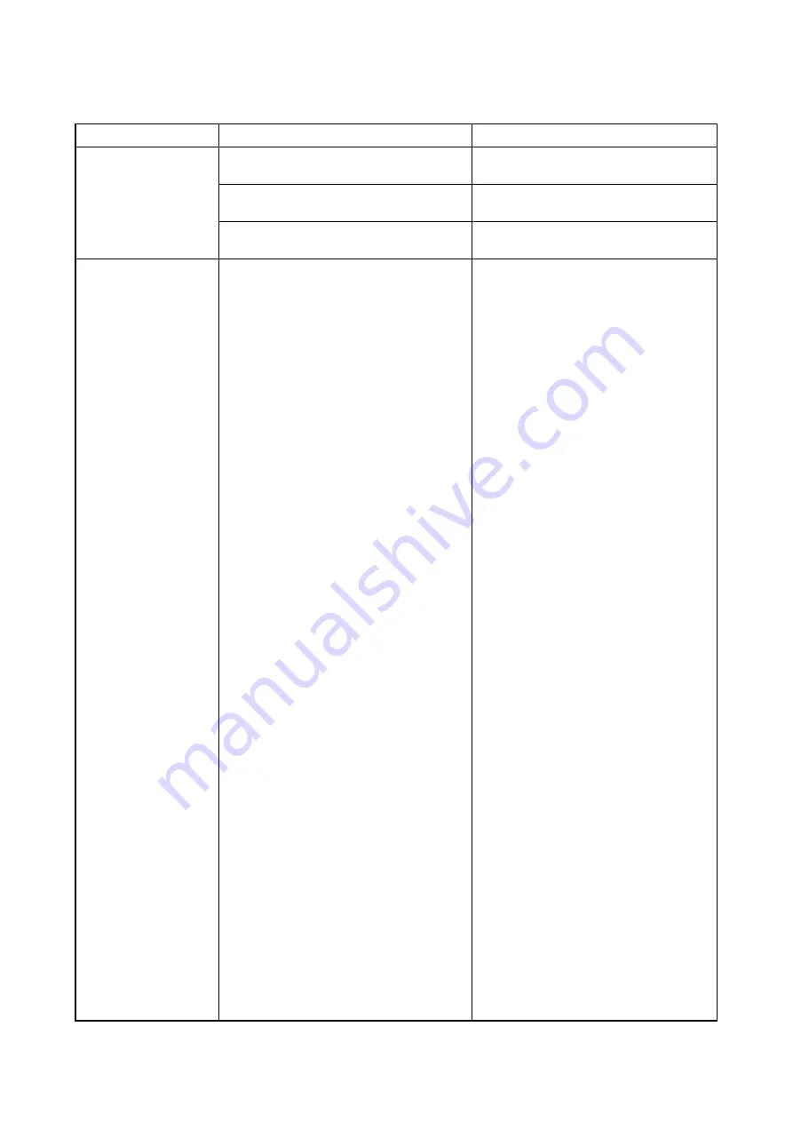
1-4-4  Mechanical problems

Problem

Causes/check procedures

Corrective measures

(1)
Paper jams.

Check if the contact between the feedshift 
roller and feedshift pulleys is correct.

Check and remedy.

Check if the contact between the feedshift 
roller and press roller is correct.

Check and remedy.

Check if the contact between the eject roller 
and eject pulleys is correct.

Check and remedy.

(2)
Abnormal noise is heard.

Check if the rollers and gears operate 
smoothly.

Grease the bearings and gears.

Содержание DF 420

Страница 1: ...Service Manual Document Finisher DF 420 First Edition Date 04 08 2009 3MJSM060 ...

Страница 2: ...Service Manual Document Finisher DF 420 First Edition Date 04 08 2009 3MJSM060 ...

Страница 3: ...icials for details in your area for proper disposal ATTENTION IL Y A UN RISQUE D EXPLOSION SI LA BATTERIE EST REMPLACEE PAR UN MODELE DE TYPE INCORRECT METTRE AU REBUT LES BATTERIES UTILISEES SELON LES INSTRUC TIONS DONNEES Il peut être illégal de jeter les batteries dans des eaux d égout municipales Vérifiez avec les fonc tionnaires municipaux de votre région pour les détails concernant des déche...

Страница 4: ...Revision history Revision Date Replaced pages Remarks ...

Страница 5: ...This page is intentionally left blank ...

Страница 6: ...rsonnel to ensure the safety of their customers their machines as well as themselves during maintenance activities Service personnel are advised to read this booklet carefully to familiarize themselves with the warnings and precautions described here before engaging in maintenance activities ...

Страница 7: ... this symbol CAUTION Bodily injury or damage to property may result from insufficient attention to or incorrect compliance with warning messages using this symbol Symbols The triangle symbol indicates a warning including danger and caution The specific point of attention is shown inside the symbol General warning Warning of risk of electric shock Warning of high temperature indicates a prohibited ...

Страница 8: ... or dusty place This may cause fire or electric shock Do not install the copier near a radiator heater other heat source or near flammable material This may cause fire Allow sufficient space around the copier to allow the ventilation grills to keep the machine as cool as possible Insufficient ventilation may cause heat buildup and poor copying performance Always handle the machine by the correct l...

Страница 9: ... carefully Always check that the copier is correctly connected to an outlet with a ground connection Check that the power cable covering is free of damage Check that the power plug is dust free If it is dirty clean it to remove the risk of fire or electric shock Never attempt to disassemble the optical unit in machines using lasers Leaking laser light may damage eyesight Handle the charger section...

Страница 10: ...r trapped wire and missing screws Check that all the caution labels that should be present on the machine according to the instruction handbook are clean and not peeling Replace with new ones if necessary Handle greases and solvents with care by following the instructions below Use only a small amount of solvent at a time being careful not to spill Wipe spills off completely Ventilate the room wel...

Страница 11: ...This page is intentionally left blank ...

Страница 12: ... 1 4 4 Mechanical problems 1 4 6 1 5 Assembly and Disassembly 1 5 1 Precautions for assembly and disassembly 1 5 1 1 Precautions 1 5 1 2 Adjusting the positions of the front side registration cursor rear side registration cursor and trailing edge registration cursor reference 1 5 2 3 Adjusting the pressure of curl eliminator mechanism 1 5 3 2 1 Mechanical construction 2 1 1 Construction of each se...

Страница 13: ...3MJ This page is intentionally left blank ...

Страница 14: ...8K 250 sheets A4 A4R B5 Letter LetterR 16K 500 sheets Muximum sheets for stapling A3 B4 Ledger Legal Folio OfficioII 8K 20 sheets A4 A4R B5 Letter LetterR 16K 30 sheets Power source Electrically connected to the machine Dimension 325 W x 450 D x 165 H mm 12 13 16 W x 17 11 16 D x 6 1 2 H Weight 8 kg 17 6 lbs or less NOTE These specifications are subject to change without notice ...

Страница 15: ...3MJ 1 1 2 1 1 2 Parts names Figure 1 1 1 7 5 6 2 4 1 3 1 Ejected paper guide extension 2 Finisher tray 3 Ejected paper guide 4 Process table 5 Finisher tray extension 6 JAM release lever 7 Staple ...

Страница 16: ...3MJ 1 1 3 1 1 3 Machine cross section Figure 1 1 2 Machine cross section Paper path 2 1 3 1 Paper conveying section 2 Process table section 3 Eject section ...

Страница 17: ...3MJ 1 1 4 This page is intentionally left blank ...

Страница 18: ...humidity or low temperature and low humidity an abrupt change in the environmental temperature and cool or hot direct air Avoid places subject to dust and vibrations Choose a surface capable of supporting the weight of the machine Place the machine on a level surface maximum allowance inclination 1 Avoid air borne substances that may adversely affect the machine or degrade the photoconductor such ...

Страница 19: ... A 5 Accessory case 6 Finisher tray 7 Left upper cover 8 Inner cover 9 Spacer B 10 Sub staple cover 11 Front eject cover 12 Rear eject cover 13 M3 x 6 screws 14 Small pin 15 Large pin 16 Hook holder 17 Staple cartridge 18 Process table 19 Tray left pad 20 Tray right pad 21 Plastic sheet 22 Paper 23 Spacer C 24 Staple cover 25 Tray top pad 26 Installation guide 27 Barcode labels ...

Страница 20: ...MJ 1 2 3 2 Remove the tapes Procedure 1 Remove two tapes from the finisher tray Figure 1 2 2 2 Remove the tape from the paper conveying unit Figure 1 2 3 Tape Finisher tray Tape Tape Paper conveying unit ...

Страница 21: ...3MJ 1 2 4 3 Remove the tape from the process table Figure 1 2 4 Tape Process table ...

Страница 22: ...ic keys Enter 001 using the cursor up down keys or numeric keys and press the start key Enter the maintenance item number using the cursor up down keys or numeric keys The selected maintenance item is run Press the stop clear key Press the start key Start End Maintenance mode is entered The maintenance item is selected Maintenance mode is exited Repeat the same maintenance item Run another mainten...

Страница 23: ...053 Setting the adjustment of the motor speed 0 3 0 7 0 5 0 0 0 1 0 1 0 3 0 0 0 0 0 5 0 0 1 Operation panel and support equipment U246 Setting the finisher 4 4 4 1 Mode setting U342 Setting the ejection restriction ON 1 2 Other U905 Checking counts by optional devices Initial setting for executing U020 1 The item initialized for executing U020 2 The item initialized for executing U021 ...

Страница 24: ... 2 Change the screen using the cursor up down keys Completion Press the stop clear key The screen for selecting a maintenance item No is displayed Display Description MAIN Main ROM ENGINE Engine ROM LANG St Standard language ROM LANG Op Optional language ROM MAIN BOOT Boot of main ROM PRINTER Printer ROM NWS Optional network scanner ROM DP Optional DP ROM FINISHER Built in finisher ROM CASS2 Optio...

Страница 25: ...et Completion Press the stop clear key The screen for selecting a maintenance item No is displayed Maintenance item No Description Display Description Setting range Initial setting MAIN Drive motor speed adjustment 5 0 to 5 0 0 3 POLY Polygon motor speed adjustment 5 0 to 5 0 0 7 EJE Eject motor speed adjustment 5 0 to 5 0 0 5 DRUM Drum motor speed adjustment 5 0 to 5 0 0 0 BYP Motor speed adjustm...

Страница 26: ...ts or cancels restriction on the number of sheets Setting 1 Press the start key 2 Select ON or OFF using the cursor up down keys Initial setting ON Details of restriction number of sheets to be ejected continuously after the start key is pressed 3 Press the start key The setting is set Completion Press the stop clear key The screen for selecting a maintenance item No is displayed Maintenance item ...

Страница 27: ... DP Finisher Completion Press the stop clear key The screen for selecting a maintenance item No is displayed Maintenance item No Description Display Description DP Counts of optional DP FINISHER Counts of finisher Display Description ADP No of single sided originals that has passed through the DP RADP No of double sided originals that has passed through the DP Display Description CP CNT No of copi...

Страница 28: ...cified time of the paper convey ing switch PCSW turning on 15 s 81 Finisher paper entry nonarrival jam The paper conveying switch PCSW is not turned on even if a specified time has elapsed after the machine eject signal was received 2598 ms 83 Finisher paper entry jam The paper conveying switch PCSW does not turn off within specified time of its turning on when paper is con veyed to the process ta...

Страница 29: ... Extremely curled paper Change the paper Defective paper conveying switch With 5 V DC present at YC2 23 on the finisher control PWB check if YC2 21 on the finisher control PWB remains low or high when the paper conveying switch is turned on and off If it does replace the paper conveying switch 4 A paper jam in fin isher is indicated dur ing copying finisher paper entry jam Jam code 83 Defective pa...

Страница 30: ...tration home position sensor connector makes poor contact Reinsert the connector Also check for conti nuity within the connector cable If none remedy or replace the cable Defective front side registration home position sensor Replace the front side registration home position sensor Defective finisher control PWB Replace the finisher control PWB and check for correct operation C8180 Built in finish...

Страница 31: ... Replace the trailing edge registration home position sensor Defective finisher control PWB Replace the finisher control PWB and check for correct operation C8210 Built in finisher stapler problem The stapler home position sensor does not change state from nondetection to detection within 200 ms of the start of stapler motor counterclockwise forward rotation During initialization the stapler home ...

Страница 32: ...ck for broken gears and replace if any 3 Broken motor coil Check for continuity across the coil If none replace the motor 2 The feedshift sole noid does not oper ate 1 Poor contact in the con nector terminals Reinsert the connector Also check for continuity within the con nector cable If none remedy or replace the cable 2 Broken solenoid coil Check for continuity across the coil If none replace th...

Страница 33: ...oller and feedshift pulleys is correct Check and remedy Check if the contact between the feedshift roller and press roller is correct Check and remedy Check if the contact between the eject roller and eject pulleys is correct Check and remedy 2 Abnormal noise is heard Check if the rollers and gears operate smoothly Grease the bearings and gears ...

Страница 34: ... power switch before pressing the power key to off may cause damage to the equipped hard disk When handling PWBs printed wiring boards do not touch parts with bare hands The PWBs are susceptible to static charge Do not touch any PWB containing ICs with bare hands or any object prone to static charge When removing the hook of the connector be sure to release the hook Take care not to get the cables...

Страница 35: ...gistration cursor REAR Stop position of the rear side registration cursor END Stop position of the trailing edge registration cursor Setting range 0 to 8 Initial setting 4 Changing the value by 1 changes the position by 0 566 mm Decreasing the value moves the front or rear side registration cursor or trailing edge registration cursor outward increasing the value moves each cursor inward See Figure...

Страница 36: ...is performed because of strong upward curling Procedure 1 Remove the paper conveying unit from the machine 2 Loosen each two screws from the front and rear curl eliminator pressure adjusting plates respectively and then remove the plates 3 Retighten each two screws 4 Refit the all removed parts Figure 1 5 3 Paper conveying unit Curl eliminator pressure adjusting plate Curl eliminator pressure adju...

Страница 37: ...3MJ 1 5 4 This page is intentionally left blank ...

Страница 38: ...1 Paper conveying section Figure 2 1 2 Paper conveying section block diagram 11 10 13 12 6 9 8 1 14 4 3 2 5 7 1 Feedshift pulleys 2 Feedshift roller 3 Press roller 4 Press roller lift 5 Stopper 6 Upper curl eliminator roller 7 Lower curl eliminator roller 8 Feedshift claw 9 Feedshift solenoid FSSOL 10 Eject roller 11 Eject pulleys 12 Paper conveying switch PCSW 13 Actuator paper conveying switch 1...

Страница 39: ...able shifts the paper stocked in the process table to the stopper the pickup solenoid PUSOL turns on to lift the press roller and release the stopper The stack of paper on the process table is ejected to the finisher tray by the feedshift roller and eject roller Figure 2 1 3 To process table Feedshift pulleys Feedshift solenoid FSSOL Upper curl eliminator roller Pickup solenoid PUSOL Pickup soleno...

Страница 40: ...on Figure 2 1 4 Process table section Figure 2 1 5 Process table section block diagram Trailing edge registration cursor Process table Front side registration cursor Rear side registration cursor SRFHPS FSRM RSRM FINPWB TERM SRRHPS TERHPS TOCSW PTS YC5 2 YC3 5 YC5 5 YC5 8 YC3 2 TRAY TOPN FJ HP RJ HP RE HP FJ _A FJ B FJ _B FJ A RJ _A RJ B RJ _B RJ A RE _A RE B RE _B RE A YC4 5 YC4 4 YC4 3 YC4 1 YC4...

Страница 41: ...the paper conveying section In staple sort mode the front and rear side registration cursors even up the sides of the stack of paper and shift the stack toward the machine front and then the trailing edge registration cursor shifts the stack to the stapling position Figure 2 1 6 Home positions Paper registration Shifting the paper to the stapling position Trailing edge registration cursor Front si...

Страница 42: ... the stapler cam via the stapler drive gear to staple paper Figure 2 1 7 Stapler section Figure 2 1 8 Stapler section block diagram Stapler cam Stapler self priming sensor Stapler drive gear Stapler cam Stapler motor FINPWB STES STCS STHPS STSPS YC2 13 ST CART ST LOW ST HP ST MOT R ST MOT F ST SP YC2 15 YC2 19 YC2 17 YC2 12 14 YC2 16 18 STM ...

Страница 43: ...3MJ 2 1 6 This page is intentionally left blank ...

Страница 44: ...onveying section 1 Paper conveying motor PCM Drives the paper conveying section 2 Paper conveying switch PCSW Detects a paper jam in the finisher 3 Feedshift solenoid FSSOL Operates the feedshift guide of the machine 4 Pickup solenoid PUSOL Operates the press roller 1 2 3 4 Machine front Machine inside Machine rear ...

Страница 45: ...5 Rear side registration motor RSRM Drives the rear side registration cursor 6 Trailing edge registration home position sensor TERHPS Detects the trailing edge registration cursor in the home position 7 Side registration front home position sensor SRFHPS Detects the front side registration cursor in the home position 8 Side registration rear home position sensor SRRHPS Detects the rear side regist...

Страница 46: ...aple cartridge sensor STCS Detects the presence of the staple cartridge 3 Stapler home position sensor STHPS Detects the stapler in the home position 4 Stapler self priming sensor STSPS Detects the pre stapling state of the stapler 5 Stapler motor STM Drives the stapler 5 1 2 3 4 Machine front Machine inside Machine rear ...

Страница 47: ...3MJ 2 2 4 This page is intentionally left blank ...

Страница 48: ...PS SRRHPS TERHPS STES STCS STHPS STSPS DF RDY EEPROM Reset IC CPU 5V SDA SCL Machine Paper conveying unit FINPWB Buffer Stepping motor driver circuit Motor driver circuit Stepping motor driver circuit Stepping motor driver circuit Stepping motor driver circuit Driver circuit FSSOL PUSOL Staple section PCM STM FSRM RSRM TERM Sensors PCSW TOCSW Switches sensors Serial communication ...

Страница 49: ...3MJ 2 3 2 Figure 2 3 2 Finisher control PWB silk screen diagram YC7 1 2 1 6 YC3 23 24 1 YC2 YC1 YC6 1 1 7 13 2 YC5 9 1 YC4 1 15 ...

Страница 50: ... V DC PUSOL On Off 3 JCT SOL ACT O 0 24 V DC FSSOL On Off active 4 CMOT A O 0 24 V DC pulse PCM drive control signal A 5 JCT SOL 24V O 24 V DC 24 V DC power output to FSSOL 6 CMOT B O 0 24 V DC pulse PCM drive control signal B 7 PU SOL 24V O 24 V DC 24 V DC power output to PUSOL 8 CMOT _A O 0 24 V DC pulse PCM drive control signal _A 9 CMOT A 24V O 24 V DC 24 V DC power output to PCM 10 CMOT _B O ...

Страница 51: ... DC power output to RSRM 8 RJ _B O 0 24 V DC pulse RSRM drive control signal _B 9 RJ B O 0 24 V DC pulse RSRM drive control signal B 10 RJ _A O 0 24 V DC pulse RSRM drive control signal _A 11 RE A O 0 24 V DC pulse TERM drive control signal A 12 COM O 24 V DC 24 V DC power output to TERM 13 RE _B O 0 24 V DC pulse TERM drive control signal _B 14 RE B O 0 24 V DC pulse TERM drive control signal B 1...

Страница 52: ...s table section Process table Clean and grease Every service Clean the rail section and apply molycote grease EM 50L 50G Upper curl eliminator roller Clean Every service Clean with alcohol Check and clean with alcohol when user call occurs Lower curl eliminator roller Clean Every service Clean with alcohol Check and clean with alcohol when user call occurs Eject roller Clean Every service Clean wi...

Страница 53: ...T CART 13 13 13 13 1 ST MOT R ST MOT R 14 14 14 14 2 ST MOT R ST LOW 15 15 15 15 3 ST MOT F 16 16 16 16 4 ST MOT F YC8 ST SP 17 17 17 17 5 ST MOT F 1 5V ST MOT F 18 18 18 18 6 2 Vpp ST HP 19 19 19 19 7 ST CART 3 FSO ST GND 20 20 20 20 8 ST LOW 4 FSI FEED 21 21 21 21 9 ST HP 5 FEED GND 22 22 22 22 10 6 FRSTN FEED 5V 23 23 23 23 11 ST GND 7 SGND ST 5V 24 24 24 24 12 ST 5V 13 ST SP 2 FEED 1 5V 3 GND ...

Отзывы: