USR-WIFI232-B2 Hardware Manual
www.usriot.com
Jinan USR IOT Technology Limited 6 / 9
h.usriot.com
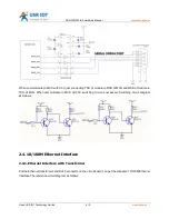
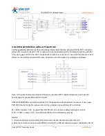
When communicate to MCU with 3.3V, just connecting TXD of module to RXD of MCU and RXD of module to
TXD of MCU. When communicate to MCU with 5V, switching circuit is necessary. Switching circuit diagram
as follows:
2.4.
10/100M Ethernet Interface
2.4.1.Ethernet Interface with Transformer
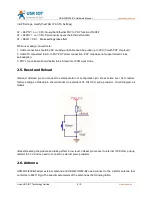
Put the Ethernet transformer and RJ45 connector on the circuit board can get the standard 10/100M Ethernet
interface.The reference circuit diagram as follows:


