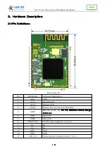


USR-C321
Low Power
Minisize
WiFi Module User Manual
20
20
20
20
/
41
41
41
41
3.
3.
3.
3.10
10
10
10.1
.1
.1
.1 Mode
Mode
Mode
Mode Introduction
Introduction
Introduction
Introduction
Mode
Mode
Mode
Mode 0:
0:
0:
0: Active
Active
Active
Active Mode
Mode
Mode
Mode
The Active mode, the system clock is 80 MHZ. Module running various peripherals.
Corresponding mode 0, that is, normal work mode, the module optimal performance.
Mode
Mode
Mode
Mode 1:
1:
1:
1: Sleep
Sleep
Sleep
Sleep Mode
Mode
Mode
Mode
Sleep mode, the system clock to 80 MHZ. Through a serial port or network packets,
gpio port output, module after awakening from entering hibernation continues to run, wake
up the response time shorter than deepsleep mode. Corresponding mode 1.
Mode
Mode
Mode
Mode 2:
2:
2:
2: Deepsleep
Deepsleep
Deepsleep
Deepsleep Mode
Mode
Mode
Mode
Module into deepsleep dormancy, reduced to 40 MHZ system clock. Might wake up via
a serial port or network packets, gpio port output, module after awakening from entering
hibernation continues to run, wake up the response time a bit longer than the sleep mode.
Than the normal operation of the lower power consumption about 5 ma. The corresponding
mode 2.
Mode
Mode
Mode
Mode 3:
3:
3:
3: LPDS
LPDS
LPDS
LPDS Mode
Mode
Mode
Mode
Module into LPDS mode, network part keep running, module gpio port output is high
impedance state. Via a serial port or network packets wake up, wake up after the restart
operation module. Corresponding mode 3.
Mode
Mode
Mode
Mode 4:
4:
4:
4: Hibernate
Hibernate
Hibernate
Hibernate Mode
Mode
Mode
Mode
Module into the hibernate mode, network and MCU are entering sleep mode, gpio port
output high impedance state, only through a serial port data. Module after the restart. Power
consumption can be achieved the uA level. Corresponding mode 4.
3.
3.
3.
3.10
10
10
10.2
.2
.2
.2 Power
Power
Power
Power Reference
Reference
Reference
Reference Table
Table
Table
Table
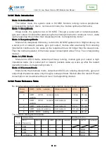
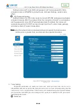
No data transmission module, the power consumption mode reference is as follows:
Power
mode
UART
、
GPIO
、
network
Wake up mode
STA
AP
0
UART
、
GPIO
、
network
working
none
18 mA
74 mA
1
UART
、
GPIO
、
network
working
Uart,network
13 mA
71 mA
2
UART
、
network working
Uart,network
9 mA
70 mA
3
UART
、
network working
Uart,network
3.5 mA
70 mA
4
GPIO
(
RXD
)
working
Uart(RXD)
24 uA
24 uA
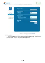
The mode to distinguish the table:
Powe
r
mode
Still working
Wakeup source
Run
frequency
MCU
WIFI
UART
GPIO
network
UART
GPIO
network
0
80M
�
�
�
�
�
1
80M
�
�
�
�
�
�
RXD
�
2
40M
�
�
�
�
�
�
RXD
�
3
32.768Khz
�
�
�
�
�
�
RXD
�


