


Vision™ OPLC™
Unitronics
3
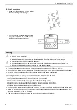
Mounting
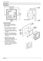
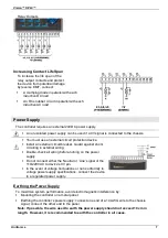
Dimensions
Panel mounting
Before you begin, note that the
mounting panel cannot be more
than 5 mm thick.
1. Make a panel cut-out measuring
92 x 92 mm (3.622” x 3.622”).
2. Slide the controller into the cut-
out, ensuring that the rubber seal
is in place.
3. Push the 2 mounting brackets
into their slots on the sides of the
controller as shown in the figure
to the right.
4. Tighten the bracket screws
against the panel. Hold the
bracket securely against the unit
while tightening the screw.
5. When properly mounted, the
controller is squarely situated in
the panel cut-out as shown in the
figure to the right.


