Unitronics V1210-T20BJ Скачать руководство пользователя страница 5

Installation Guide 

Vision™ OPLC™,V1210-T20BJ 


Unitronics 


Wiring 


  Do not touch live wires. 


  Install an external circuit breaker. Guard against short-circuiting in external wiring. 

  Use appropriate circuit protection devices. 

  Unused pins should not be connected. Ignoring this directive may damage the device. 

  Double-check all wiring before turning on the power supply. 

Caution 

  To avoid damaging the wire, do not exceed a maximum torque of 0.5 N·m (5 kgf·cm). 

  Do not use tin, solder, or any substance on stripped wire that might cause the wire 

strand to break. 

  Install at maximum distance from high-voltage cables and power equipment. 
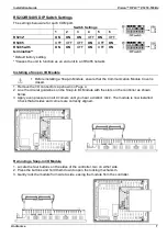
 

Wiring Procedure 

Use crimp terminals for wiring; use 26-12 AWG wire (0.13 mm 

2

–3.31 mm

2

).  

1. Strip the wire to a length of 7±0.5mm (0.250

–0.300 inches).  

2. Unscrew the terminal to its widest position before inserting a wire.  

3. Insert the wire completely into the terminal to ensure a proper connection. 

4. Tighten enough to keep the wire from pulling free. 
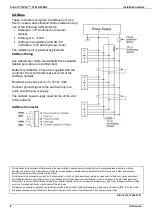
 

Power Supply 

The controller V1210-T20BJ requires either an external 12 or 24VDC power supply.  
Permissible input voltage range: 10.2-28.8VDC, with less than 10% ripple.  


  The power supply must include double insulation. Outputs must be rated as 

SELV/PELV/Class 2/Limited Power. 


Do not connect either the ‘Neutral or ‘Line’ signal of the 110/220VAC to device’s 0V pin. 


  Install an external circuit breaker. Guard against short-

circuiting in external wiring. 

  Double-check all wiring before turning on the power 

supply. 

  In the event of voltage fluctuations or non-conformity to 

voltage power supply specifications, connect the device 
to a regulated power supply. 


Earthing the OPLC  

To maximize system performance, avoid electromagnetic interference by: 

  Mounting the controller on a metal panel. 

  Connect the functional earth terminal of the OPLC, and the common and ground lines of 

I/Os, directly to the earth ground of your system.


  For ground wiring, use the shortest and thickest possible wire.


Содержание V1210-T20BJ

Страница 1: ...or remote I Os may be added via expansion port or CANbus Installation instructions and other data may be found in the module s technical specification sheet Information Mode This mode enables you to Calibrate the touchscreen View Edit operand values COM port settings RTC and screen contrast brightness settings Stop initialize and reset the PLC To enter Information Mode press the touchscreen and ma...

Страница 2: ...ution Before using this product the user must read and understand this document All examples and diagrams are intended to aid understanding and do not guarantee operation Unitronics accepts no responsibility for actual use of this product based on these examples Please dispose of this product according to local and national standards and regulations Only qualified service personnel should open thi...

Страница 3: ...over on the rear of the controller 1 Remove the battery cover shown on page 4 The polarity is marked on the battery holder and on the battery 2 Insert the battery ensuring that the polarity symbol on the battery is facing up aligned with the symbol on the holder 3 Replace the battery cover Mounting Dimensions Note that the LCD screen may have a single pixel that is permanently either black or whit...

Страница 4: ...he right 2 Slide the controller into the cut out ensuring that the rubber seal is in place 3 Push the 8 mounting brackets into their slots on the sides of the controller as shown in the figure to the right 4 Tighten the bracket screws against the panel Hold the bracket securely against the unit while tightening the screw 5 When properly mounted the controller is squarely situated in the panel cut ...

Страница 5: ...to the terminal to ensure a proper connection 4 Tighten enough to keep the wire from pulling free Power Supply The controller V1210 T20BJ requires either an external 12 or 24VDC power supply Permissible input voltage range 10 2 28 8VDC with less than 10 ripple The power supply must include double insulation Outputs must be rated as SELV PELV Class 2 Limited Power Do not connect either the Neutral ...

Страница 6: ...nicate with serial devices and applications such as SCADA Use RS485 to create a multi drop network containing up to 32 devices Pinouts The pinouts below show PLC port signals To connect a PC to a port that is set to RS485 remove the RS485 connector and connect the PC to the PLC via the programming cable Note that this is possible only if flow control signals are not used which is the standard case...

Страница 7: ...sure that the Communication Module Cover is closed 1 Remove the I O connector cap shown on Page 4 2 Line the circular guidelines on the Snap in I O Module with the slots on the controller as shown below 3 Apply even pressure on all 4 corners until you hear a distinct click The module is now installed Check that all sides and corners are correctly aligned Removing a Snap in I O Module 1 Locate the ...

Страница 8: ...at any time at its sole discretion and without notice to discontinue or change the features designs materials and other specifications of its products and to either permanently or temporarily withdraw any of the forgoing from the market All information in this document is provided as is without warranty of any kind either expressed or implied including but not limited to any implied warranties of ...

Отзывы: