IO-DI8-RO8, IO-DI8-RO8-L
I / O E x p a n s i o n M o d u l e s
5/05
6
Unitronics
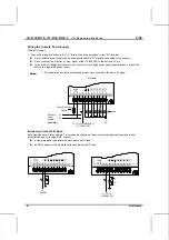
Wiring the Outputs’ Power Supply
Wiring DC supply
1 Connect the "positive" cable to the "+V" terminal, and the “negative” to the "0V" terminal.
A non-isolated power supply can be used provided that a 0V signal is connected to the chassis.
Do not connect the ‘Neutral’ or ‘Line’ signal of the 110/220VAC to the device’s 0V pin.
In the event of voltage fluctuations or non-conformity to voltage power supply specifications, connect the
device to a regulated power supply.
Notes:
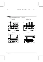
1. The adapter and output’s power supply must be connected to the same 0V signal.
Outputs
Circuit Protection
Device
L1, L2, L3 (115/230VAC)
+V (12/24VDC)
Output's
power
supply
0V
+V
N
0V
Load
See Note 1
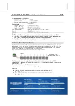
Increasing Contact Life Span
Both modules have 8 relay outputs. To increase the life span of these contacts and protect the module from
potential damage by reverse EMF, connect:
a clamping diode in parallel with each inductive DC load,
an RC snubber circuit in parallel with each inductive
AC
load.
0V
(24VDC)
+V
L1, L2, L3
(115/230VAC)
N
R
C

