


77
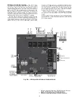
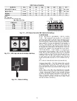
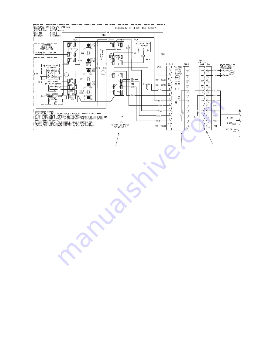
Fig. 129 — EconoMi$er
®
IV Wiring
Step 11 — Adjust Factory-Installed Options
SMOKE DETECTORS — Smoke detector(s) will be con-
nected at the Controls Connections Board, at terminals marked
“Smoke Shutdown.” Cut jumper JMP 3 when ready to ener-
gize unit.
ECONOMI$ER IV OCCUPANCY SWITCH — Refer to
Fig. 129 for general EconoMi$er IV wiring. External occupan-
cy control is managed through a connection on the Controls
Connections Board.
If external occupancy control is desired, connect a time
clock or remotely controlled switch (closed for Occupied, open
for Unoccupied sequence) at terminals marked OCCUPANCY.
Cut jumper JMP 2 to complete the installation.
Step 12 — Install Accessories —
Available acces-
sories include:
• Roof Curb
• Thru-base connection kit (must be installed before unit is
set on curb)
• Manual outside air damper
• Two-Position motorized outside air damper
• EconoMi$er IV (with control and integrated barometric
relief)
• EconoMi$er2 (without control/for external signal and
integrated barometric relief)
• Power Exhaust
• Differential dry-bulb sensor (EconoMi$er IV)
• Outdoor enthalpy sensor
• Differential enthalpy sensor
• Electric Heaters
• Single point kits
• Low Ambient Controls
• Thermostat / Sensors
• CO
2
sensor
• DDC interface (PremierLink controller)
• Louvered hail guard
• Phase monitor control
Refer to separate installation instructions for information on
installing these accessories.
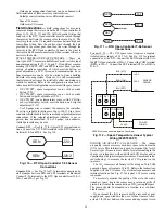
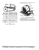
Step 13 — Check Belt Tension —
Measure the belt
span length as shown in Fig. 130. Calculate the required deflec-
tion by multiplying the belt span length by
1
/
64
. For example, if
the belt span length is 32 inches: 32 x
1
/
64
=
1
/
2
inch deflection.
BELT FORCE — DEFLECTION METHOD — Check the
belt tension with a spring-force belt force deflection gauge
(available from drive belt manufacturer).
1. Place a straightedge along the belt between the two
pulleys. Measure the distance between the motor shaft
and the blower shaft.
2. Set the tension gauge to the desired tension (see Table 1
in Fig. 130). Place the large O-ring at that point.
3. Press the tension checker downward on the belt until the
large O-ring is at the bottom of the straightedge.
4. Adjust the belt tension as needed.
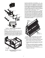
Adjust belt tension by loosing the motor mounting plate
front bolts and rear bolt (see Fig. 131) and slide the plate to-
wards the fan (to reduce tension) or away from the fan (to in-
crease tension). Ensure the blower shaft and motor shaft are
parallel to each other (pulleys aligned). Tighten all bolts se-
curely when finished.
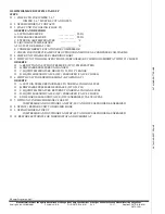
Economizer
2 Position Damper
Unit Without Economizer or
2 Position Damper
Содержание Carrier WeatherMaker 50TC A08 Series
Страница 4: ...4 Fig 2 Unit Dimensional Drawing Size 08 09 12 Units...
Страница 5: ...5 Fig 2 Unit Dimensional Drawing Size 08 09 12 Units cont...
Страница 6: ...6 Fig 3 Unit Dimensional Drawing Size 14 Unit...
Страница 7: ...7 Fig 3 Unit Dimensional Drawing Size 14 Unit cont...
Страница 9: ...9 Fig 4 Unit Dimensional Drawing Size 16 Unit cont...
Страница 13: ...13 Fig 8 Roof Curb Details Size 16 Unit...
Страница 33: ...33 Fig 62 Typical Humidi MiZer Adaptive Dehumidification System Humidistat Wiring 50TC 08 14 Unit Sizes...
Страница 34: ...34 Fig 63 Typical Humidi MiZer Adaptive Dehumidification System Humidistat Wiring 50TC 16 Unit Sizes HUMIDISTAT...
Страница 50: ...50 Fig 73 50TC 16 Control Box Component PremierLink Locations...
Страница 51: ...51 Fig 74 Typical PremierLink Control Wiring Diagram...
Страница 52: ...52 Fig 75 Typical PremierLink Control Wiring Diagram with Humidi MiZer System Option...
Страница 64: ...64 Fig 106 Typical RTU Open Controller Wiring Diagram 50TC 08 14 Size Units...
Страница 65: ...65 Fig 107 Typical RTU Open Controller Wiring Diagram 50TC 16 Size Unit...
Страница 66: ...66 Fig 108 Typical RTU Open Controller Wiring Diagram with Humidi MiZer System Option 50TC 08 14 Size Units...
Страница 67: ...67 Fig 109 Typical RTU Open Controller Wiring Diagram with Humidi MiZer System Option 50TC 16 Size Units...